Toyota Venza: Stop Light Control Relay Malfunction (C1380/64)
DESCRIPTION
Upon receiving the hill-start assist control operating signal from the skid control ECU, the relay contact turns on and the stop light comes on.
|
DTC Code |
DTC Detection Condition |
Trouble Area |
|---|---|---|
|
C1380/64 |
Either of the following is detected:
|
|
WIRING DIAGRAM
Refer to DTC C1249/49 (See page .gif) ).
).
CAUTION / NOTICE / HINT
HINT:
When DTC C1249/49 is output together with DTC C1380/64, inspect and repair the
trouble areas indicated by DTC C1249/49 first (See page
).
PROCEDURE
|
1. |
CHECK STOP LIGHT OPERATION |
(a) Check that the stop lights come on when the brake pedal is depressed, and go off when the brake pedal is released.
OK:
|
Condition |
Illumination Condition |
|---|---|
|
Brake pedal depressed |
ON |
|
Brake pedal released |
OFF |
| NG | .gif) |
INSPECT STOP LIGHT CIRCUIT |
|
.gif)
|
2. |
READ VALUE USING TECHSTREAM (STOP LIGHT SWITCH) |
(a) Connect the Techstream to the DLC3.
(b) Turn the ignition switch to ON.
(c) Select the Data List on the Techstream (See page
).
ABS/VSC/TRAC
|
Tester Display |
Measurement Item/Range |
Normal Condition |
Diagnostic Note |
|---|---|---|---|
|
Stop Light SW |
Stop light switch / ON or OFF |
ON: Brake pedal depressed OFF: Brake pedal released |
- |
(d) Check that the stop light switch condition observed on the Techstream changes according to brake pedal operation.
OK:
The Techstream displays ON or OFF according to brake pedal operation.
| NG | |
GO TO STEP 9 |
|
|
3. |
PERFORM ACTIVE TEST USING TECHSTREAM (STOP LIGHT CONTROL (BRK) RELAY) |
(a) Select the Data List on the Techstream (See page
).
ABS/VSC/TRAC
|
Tester Display |
Measurement Item/Range |
Normal Condition |
Diagnostic Note |
|---|---|---|---|
|
Stop Light Relay |
Stop light control (BRK) relay / ON or OFF |
ON: Relay on OFF: Relay off |
- |
|
Stop Light Relay Output |
Stop light control (BRK) relay output / ON or OFF |
ON: Relay output on OFF: Relay output off |
- |
(b) Select the Active Test on the Techstream (See page
).
ABS/VSC/TRAC
|
Tester Display |
Test Part |
Control Range |
Diagnostic Note |
|---|---|---|---|
|
Stop Light Relay |
Stop light control (BRK) relay |
Relay ON/OFF |
Stop lights come on |
(c) Perform the Active Test of the stop light control (BRK) relay using the Techstream.
(d) Check for stop light control (BRK) relay operation using Data List and stop light operation by performing an Active Test.
|
Result |
Proceed to |
|---|---|
|
Data List content and stop light operation are normal |
A |
|
Data List content is normal but stop lights do not turn on or off |
B |
| B | |
GO TO STEP 6 |
|
|
4. |
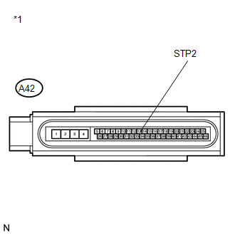
INSPECT SKID CONTROL ECU (STP2 TERMINAL) |
|
(a) Turn the ignition switch off. |
|
(b) Make sure that there is no looseness at the locking part and the connecting part of the connector.
(c) Disconnect the skid control ECU connector.
(d) Measure the voltage according to the value(s) in the table below.
Standard Voltage:
|
Tester Connection |
Switch Condition |
Specified Condition |
|---|---|---|
|
A42-13 (STP2) - Body ground |
Stop light switch ON (Brake pedal depressed) |
8 to 14 V |
|
A42-13 (STP2) - Body ground |
Stop light switch OFF (Brake pedal released) |
Below 1.5 V |
|
*1 |
Front view of wire harness connector (to Brake Actuator (Skid Control ECU)) |
| NG | |
REPAIR OR REPLACE HARNESS OR CONNECTOR (STP2 CIRCUIT) |
|
|
5. |
RECONFIRM DTC |
(a) Reconnect the skid control ECU connector.
(b) Clear the DTCs (See page ).
(c) Start the engine.
(d) Perform a road test.
(e) Check if the same DTC is recorded (See page
).
|
Result |
Proceed to |
|---|---|
|
DTC (C1380/64) is not output |
A |
|
DTC (C1380/64) is output |
B |
| A | |
CHECK FOR INTERMITTENT PROBLEMS |
| B | |
REPLACE BRAKE ACTUATOR ASSEMBLY |
|
6. |
INSPECT STOP LIGHT CONTROL (BRK) RELAY |
|
(a) Turn the ignition switch off. |
|
.png)
(b) Remove the stop light control (BRK) relay.
(c) Measure the resistance according to the value(s) in the table below.
Standard Resistance:
|
Tester Connection |
Condition |
Specified Condition |
|---|---|---|
|
3 - 4 |
Voltage is not applied between terminals 1 and 2 |
Below 1 Ω |
|
3 - 5 |
Voltage is not applied between terminals 1 and 2 |
10 kΩ or higher |
|
3 - 4 |
Voltage is applied between terminals 1 and 2 |
10 kΩ or higher |
|
3 - 5 |
Voltage is applied between terminals 1 and 2 |
Below 1 Ω |
|
*1 |
Stop Light Control (BRK) Relay |
| NG | |
REPLACE STOP LIGHT CONTROL (BRK) RELAY |
|
|
7. |
INSPECT ENGINE ROOM RELAY BLOCK (POWER SOURCE TERMINAL) |
|
(a) Measure the voltage according to the value(s) in the table below. Standard Voltage:
|
|
| NG | |
REPAIR OR REPLACE HARNESS OR CONNECTOR (POWER SOURCE CIRCUIT) |
|
|
8. |
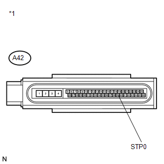
INSPECT SKID CONTROL ECU (STP0 TERMINAL) |
|
(a) Install the stop light control (BRK) relay. |
|
(b) Make sure that there is no looseness at the locking part and the connecting part of the connector.
(c) Disconnect the skid control ECU connector.
(d) Turn the ignition switch to ON.
(e) Measure the voltage according to the value(s) in the table below.
Standard Voltage:
|
Tester Connection |
Switch Condition |
Specified Condition |
|---|---|---|
|
A42-39 (STP0) - Body ground |
Ignition switch ON |
11 to 14 V |
|
*1 |
Front view of wire harness connector (to Brake Actuator (Skid Control ECU)) |
| OK | |
REPLACE BRAKE ACTUATOR ASSEMBLY |
| NG | |
REPAIR OR REPLACE HARNESS OR CONNECTOR (STP0 CIRCUIT) |
|
9. |
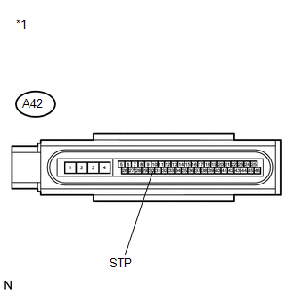
INSPECT SKID CONTROL ECU (STP TERMINAL) |
|
(a) Turn the ignition switch off. |
|
(b) Make sure that there is no looseness at the locking part and the connecting part of the connector.
(c) Disconnect the skid control ECU connector.
(d) Measure the voltage according to the value(s) in the table below.
Standard Voltage:
|
Tester Connection |
Switch Condition |
Specified Condition |
|---|---|---|
|
A42-30 (STP) - Body ground |
Stop light switch ON (Brake pedal depressed) |
8 to 14 V |
|
A42-30 (STP) - Body ground |
Stop light switch OFF (Brake pedal released) |
Below 1.5 V |
|
*1 |
Front view of wire harness connector (to Brake Actuator (Skid Control ECU)) |
| OK | |
REPLACE BRAKE ACTUATOR ASSEMBLY |
| NG | |
REPAIR OR REPLACE HARNESS OR CONNECTOR (STP CIRCUIT) |
 Control Module Communication Bus OFF (U0073/94,U0100/65,U0123/62,U0124/95,U0126/63)
DESCRIPTION
The skid control ECU receives the signals from the ECM, steering angle sensor,
and yaw rate and acceleration sensor via the CAN communication system.
DTC Code
DTC ...
 Skid Control ECU Malfunction (C1300/62)
DESCRIPTION
The skid control ECU outputs this DTC, if malfunctions are found in the circuit
inside the ECU by self diagnosis.
DTC Code
DTC Detection Condition
Trou ...
Other materials about Toyota Venza:
Security Indicator Light Circuit
DESCRIPTION
Even when the theft deterrent system is in the disarmed state, the security indicator
blinks due to a signal output from the immobiliser system. The security indicator
blinks continuously due to a continuous signal received from the immobilise ...
Disassembly
DISASSEMBLY
CAUTION / NOTICE / HINT
HINT:
Use the same procedure for the RH side and the LH side.
The procedure listed below is for the LH side.
PROCEDURE
1. REMOVE REAR WHEEL
2. REMOVE REAR AXLE SHAFT NUT (for AWD)
NOTICE:
Perform th ...
TC and CG Terminal Circuit
DESCRIPTION
DTC output mode is set by connecting terminals TC and CG of the DLC3.
DTCs are displayed by blinking of the SRS warning light.
HINT:
When each warning light stays blinking, a ground short in the wiring
of terminal TC of the DLC3 or ...

0.1484