Toyota Venza: Brake Switch "B" Circuit High (P0724)
DESCRIPTION
The purpose of this circuit is to prevent the engine from stalling when brakes are suddenly applied while driving in lock-up condition.
When the brake pedal is depressed, the stop light switch sends a signal to the ECM. Then the ECM cancels the operation of the lock-up clutch while braking is in progress.
|
DTC No. |
DTC Detection Condition |
Trouble Area |
|---|---|---|
|
P0724 |
The stop light switch remains on even when the vehicle repeats 5 cycles of STOP (less than 3 km/h [1.86 mph]) and GO (30 km/h [18.65 mph] or more) (2 trip detection logic). |
|
MONITOR DESCRIPTION
This DTC indicates that the stop light switch remains on. When the stop light switch remains on during "stop and go" driving, the ECM interprets this as a fault in the stop light switch. The ECM turns on MIL and stores the DTC. The vehicle must stop (less than 3 km/h [1.86 mph]) and go (30 km/h [18.65 mph] or more) 5 times during 2 driving cycles, in order to detect a malfunction.
MONITOR STRATEGY
|
Related DTCs |
P0724: Brake Pedal Position Switch Verify Input Signal |
|
Required Sensors/Components (Main) |
Stop light switch |
|
Required Sensors/Components (Related) |
Speed sensor |
|
Frequency of Operation |
Continuous |
|
Duration |
5 times |
|
MIL Operation |
2 driving cycles |
|
Sequence of Operation |
None |
TYPICAL ENABLING CONDITIONS
|
Monitor runs whenever the following DTCs are not stored |
None |
|
All of the following conditions are met |
- |
|
Battery voltage |
8 V or higher |
|
Starter |
Off |
|
Ignition switch |
ON |
|
GO: Vehicle speed |
30 km/h (18.65 mph) or more |
|
STOP: Vehicle speed |
Less than 3 km/h (1.86 mph) |
TYPICAL MALFUNCTION THRESHOLDS
|
Brake pedal position switch |
On stuck |
CONFIRMATION DRIVING PATTERN
- Connect the Techstream to the DLC3.
- Turn the ignition switch to ON and turn the Techstream on.
- Clear the DTCs (even if no DTCs are stored, perform the clear DTC procedure)
(See page
.gif) ).
). - Turn the ignition switch off and wait for at least 30 seconds.
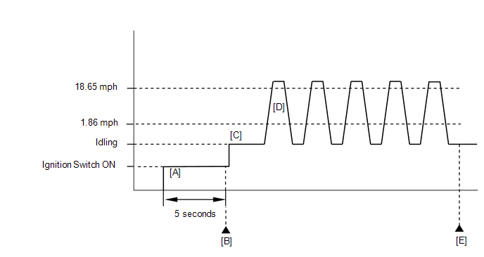
- Turn the ignition switch to ON and turn the Techstream on [A].
- Wait 5 seconds.
- Enter the following menus: Powertrain / Engine / Trouble Codes [B].
- Read the Pending DTCs.
HINT:
- If a pending DTC is output, the system is malfunctioning.
- If a pending DTC is not output, perform the following procedure.
- Enter the following menus: Powertrain / Engine / Utility / All Readiness.
- Input the DTC: P0724.
- Check the DTC judgment result.
Techstream Display
Description
NORMAL
- DTC judgment completed
- System normal
ABNORMAL
- DTC judgment completed
- System abnormal
INCOMPLETE
- DTC judgment not completed
- Perform driving pattern after confirming DTC enabling conditions
N/A
- Unable to perform DTC judgment
- Number of DTCs which do not fulfill DTC preconditions has reached ECU memory limit
HINT:
- If the judgment result shows NORMAL, the system is normal.
- If the judgment result shows ABNORMAL, the system has a malfunction.
- If the judgment result shows INCOMPLETE or N/A, perform steps [C] through [E].
- Start the engine [C].
- Accelerate the vehicle to 30 km/h (18.65 mph) or more, depress the brake
pedal and decelerate the vehicle to 3 km/h (1.86 mph) or less [D]. Repeat
step [D] 5 times.
CAUTION:
When performing the confirmation driving pattern, obey all speed limits and traffic laws.
- Check the DTC judgment result [E].
- If the test result is INCOMPLETE or N/A and no pending DTC is output,
perform a universal trip and check for permanent DTCs (See page
).
HINT:
- If a permanent DTC is output, the system is malfunctioning.
- If no permanent DTC is output, the system is normal.
WIRING DIAGRAM
Refer to DTC P0504 (See page ).
CAUTION / NOTICE / HINT
NOTICE:
Inspect the fuses for circuits related to this system before performing the following inspection procedure.
HINT:
Read freeze frame data using the Techstream. The ECM records vehicle and driving condition information as freeze frame data the moment a DTC is stored. When troubleshooting, freeze frame data can help determine if the vehicle was moving or stationary, if the engine was warmed up or not, if the air fuel ratio was lean or rich, and other data from the time the malfunction occurred.
PROCEDURE
|
1. |
READ VALUE USING TECHSTREAM (STOP LIGHT SWITCH) |
(a) Connect the Techstream to the DLC3.
(b) Turn the ignition switch to ON.
(c) Turn the Techstream on.
(d) Enter the following menus: Powertrain / Engine / Data List / Stop Light Switch.
(e) Read the values displayed on the Techstream.
OK:
|
Item |
Measurement Item/Range (display) |
Normal Condition |
|---|---|---|
|
Stop Light Switch |
Stop light switch status: ON or OFF |
|
| OK | .gif) |
CHECK FOR INTERMITTENT PROBLEMS |
|
.gif)
|
2. |
INSPECT STOP LIGHT SWITCH ASSEMBLY |
(a) Inspect the stop light switch assembly (See page
).
| NG | |
REPLACE STOP LIGHT SWITCH ASSEMBLY |
|
|
3. |
CHECK HARNESS AND CONNECTOR (STOP LIGHT SWITCH - ECM) |
(a) Disconnect the ECM connector.
.png)
(b) Turn the ignition switch to ON.
(c) Measure the voltage according to the value(s) in the table below.
Standard Voltage:
|
Tester Connection |
Condition |
Specified Condition |
|---|---|---|
|
A49-29 (STP) - Body ground |
Brake pedal released |
Below 1.5 V |
|
Brake pedal depressed |
7.5 to 14 V |
|
*a |
Brake pedal depressed |
*b |
Brake pedal released |
|
*c |
Front view of wire harness connector (to ECM) |
- |
- |
| OK | |
REPLACE ECM |
| NG | |
REPAIR OR REPLACE HARNESS OR CONNECTOR |
 Transmission Range Sensor Circuit Malfunction (PRNDL Input) (P0705)
DESCRIPTION
The park/neutral position switch assembly detects the shift lever position and
sends signals to the ECM.
DTC No.
DTC Detection Condition
Trouble Area
...
 Engine Stall History (P1603,P1605)
DESCRIPTION
P1603
After starting the engine, this DTC is stored when the engine stops without the
ignition switch being operated.
Using the Techstream, the conditions present when the DTC was sto ...
Other materials about Toyota Venza:
Installation
INSTALLATION
PROCEDURE
1. INSTALL NO. 2 COOLING FAN MOTOR
(a) Install the No. 2 cooling fan motor with the 3 screws.
Torque:
w/o Towing package :
2.6 N·m {26 kgf·cm, 23 in·lbf}
w/ Towing package :
3.9 N·m {40 kgf·cm, 35 in ...
Door Courtesy Light
Components
COMPONENTS
ILLUSTRATION
Removal
REMOVAL
PROCEDURE
1. REMOVE COURTESY LIGHT ASSEMBLY
(a) Using a screwdriver wrapped with protective tape, disengage the claw.
Text in Illustration
*1
Pro ...
Portable Player cannot be Connected Manually/Automatically
CAUTION / NOTICE / HINT
HINT:
Some versions of "Bluetooth" compatible audio players may not function properly,
or the functions may be limited using the radio and display receiver assembly, even
if the portable audio player itself can play file ...

0.1401