Toyota Venza: Steering Lock Motor Drive Power Circuit
DESCRIPTION
The steering lock ECU (steering lock actuator assembly) is connected to the power management control ECU. The steering lock ECU (steering lock actuator assembly) cannot activate the motor unless it receives permission signals from both ECUs. (The power management control ECU permits the steering lock ECU (steering lock actuator assembly) to supply power to activate the motor.)
WIRING DIAGRAM
.png)
PROCEDURE
|
1. |
CHECK VEHICLE CONDITION |
(a) Check the problem symptom of the steering lock system.
|
Condition |
Proceed to |
|---|---|
|
Steering lock cannot be released. |
A |
|
Steering cannot be locked. |
B |
| B | .gif) |
GO TO STEP 6 |
|
.gif)
|
2. |
READ VALUE USING TECHSTREAM |
(a) Connect the Techstream to the DLC3.
(b) Turn the engine switch on (IG).
(c) Turn the Techstream on.
(d) Check the steering lock command reception record. Enter the following menus: Body Electrical / Smart Key / Data List.
Smart Key|
Tester Display |
Measurement Item/Range |
Normal Condition |
Diagnostic Note |
|---|---|---|---|
|
Lock/Unlock Receive |
Steering lock command reception record / Yes or No |
Yes: Steering lock/unlock signal received No: Steering lock/unlock signal not received |
- |
(e) Check if steering unlock command reception is confirmed.
OK:
"YES" is displayed on the Techstream.
| NG | |
CHECK SMART KEY SYSTEM (for Start Function) |
|
|
3. |
INSPECT STEERING LOCK ECU (STEERING LOCK ACTUATOR ASSEMBLY) |
|
(a) Measure the voltage according to the value(s) in the table below. Standard Voltage:
|
|
.png)
|
*1 |
Component with harness connected (Steering Lock ECU (Steering Lock Actuator Assembly)) |
| OK | |
PROCEED TO NEXT CIRCUIT INSPECTION SHOWN IN PROBLEM SYMPTOMS TABLE |
|
|
4. |
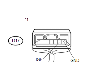
CHECK HARNESS AND CONNECTOR (STEERING LOCK ECU - BODY GROUND) |
|
(a) Disconnect the D17 connector from the steering lock ECU (steering lock actuator assembly). |
|
.png)
(b) Measure the resistance according to the value(s) in the table below.
Standard Resistance:
|
Tester Connection |
Condition |
Specified Condition |
|---|---|---|
|
D17-1 (GND) - Body ground |
Always |
Below 1 Ω |
|
*1 |
Front view of wire harness connector (to Steering Lock ECU (Steering Lock Actuator Assembly)) |
| NG | |
REPAIR OR REPLACE HARNESS OR CONNECTOR |
|
|
5. |
CHECK HARNESS AND CONNECTOR (STEERING LOCK ECU - POWER MANAGEMENT CONTROL ECU) |
|
(a) Disconnect the D43 connector from the power management control ECU. |
|
.png)
(b) Measure the resistance according to the value(s) in the table below.
Standard Resistance:
|
Tester Connection |
Condition |
Specified Condition |
|---|---|---|
|
D17-3 (IGE) - D43-8 (SLR+) |
Always |
Below 1 Ω |
|
D17-3 (IGE) - Body ground |
Always |
10 kΩ or higher |
|
*1 |
Front view of wire harness connector (to Steering Lock ECU (Steering Lock Actuator Assembly)) |
|
*2 |
Front view of wire harness connector (to Power Management Control ECU) |
| OK | |
REPLACE POWER MANAGEMENT CONTROL ECU |
| NG | |
REPAIR OR REPLACE HARNESS OR CONNECTOR |
|
6. |
INSPECT STEERING LOCK ECU (STEERING LOCK ACTUATOR ASSEMBLY) |
|
(a) Measure the voltage according to the value(s) in the table below. Standard Voltage:
|
|
|
*1 |
Component with harness connected (Steering Lock ECU (Steering Lock Actuator Assembly)) |
| OK | |
PROCEED TO NEXT SUSPECTED AREA SHOWN IN PROBLEM SYMPTOMS TABLE |
|
|
7. |
CHECK HARNESS AND CONNECTOR (STEERING LOCK ECU - POWER MANAGEMENT CONTROL ECU) |
|
(a) Disconnect the D17 connector from the steering lock ECU (steering lock actuator assembly). |
|
(b) Disconnect the D43 connector from the power management control ECU.
(c) Measure the resistance according to the value(s) in the table below.
Standard Resistance:
|
Tester Connection |
Condition |
Specified Condition |
|---|---|---|
|
D17-3 (IGE) - D43-8 (SLR+) |
Always |
Below 1 Ω |
|
D17-3 (IGE) - Body ground |
Always |
10 kΩ or higher |
|
*1 |
Front view of wire harness connector (to Steering Lock ECU (Steering Lock Actuator Assembly)) |
|
*2 |
Front view of wire harness connector (to Power Management Control ECU) |
| OK | |
REPLACE POWER MANAGEMENT CONTROL ECU |
| NG | |
REPAIR OR REPLACE HARNESS OR CONNECTOR |
 Open / Short in Steering Lock ECU (B2781)
DESCRIPTION
If the steering lock ECU (steering lock actuator assembly) determines that there
is a malfunction inside the ECU, it outputs this DTC. Diagnostic communication between
the steering lo ...
 Unlock Position Sensor Signal Circuit
DESCRIPTION
The unlock position sensor is one of the components comprising the steering lock
ECU (steering lock actuator assembly). The sensor switch contact closes when the
steering lock is rele ...
Other materials about Toyota Venza:
Unmatched Key Code (B2795)
DESCRIPTION
This DTC is stored when a key with a key code that has not been registered in
the ECU is inserted into the ignition key cylinder.
DTC No.
DTC Detection Condition
Trouble Area
B2795
Ke ...
Camshaft Position "B" Actuator Circuit / Open (Bank 1) (P0013)
DESCRIPTION
The Variable Valve Timing (VVT) system adjusts the exhaust valve timing to improve
driveability. The engine oil pressure turns the VVT controller to adjust the valve
timing.
The camshaft timing oil control valve is a solenoid valve and switch ...
Disassembly
DISASSEMBLY
PROCEDURE
1. REMOVE STEERING RACK BOOT CLIP (for LH Side)
(a) Using pliers, remove the steering rack boot clip.
2. REMOVE STEERING RACK BOOT CLIP (for RH Side)
HINT:
Perform the same procedure as for the LH side.
3. REMOVE NO. 2 STEERING RAC ...

0.1529