Toyota Venza: Unlock Position Sensor Signal Circuit
DESCRIPTION
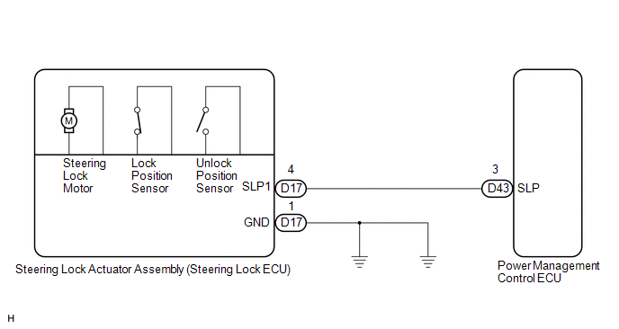
The unlock position sensor is one of the components comprising the steering lock ECU (steering lock actuator assembly). The sensor switch contact closes when the steering lock is released. The steering lock release signal is then sent to the power management control ECU. Upon receiving the signal, the ECU permits engine start. This prevents the engine from being started with the steering wheel locked.
WIRING DIAGRAM
CAUTION / NOTICE / HINT
HINT:
After replacing the steering lock ECU (steering lock actuator assembly), confirm
the Initialization of the steering lock (See page
.gif) ).
).
PROCEDURE
|
1. |
INSPECT STEERING LOCK ECU (STEERING LOCK ACTUATOR ASSEMBLY) |
|
(a) Measure the voltage according to the value(s) in the table below. Standard Voltage:
|
|
| OK | .gif) |
REPLACE STEERING LOCK ECU (STEERING LOCK ACTUATOR ASSEMBLY) |
|
.gif)
|
2. |
CHECK HARNESS AND CONNECTOR (STEERING LOCK ECU - POWER MANAGEMENT CONTROL ECU) |
|
(a) Disconnect the D17 connector from the steering lock ECU (steering lock actuator assembly). |
|
(b) Disconnect the D43 connector from the power management control ECU.
(c) Measure the resistance according to the value(s) in the table below.
Standard Resistance:
|
Tester Connection |
Condition |
Specified Condition |
|---|---|---|
|
D17-4 (SLP1) - D43-3 (SLP) |
Always |
Below 1 Ω |
|
D17-4 (SLP1) - Body ground |
Always |
10 kΩ or higher |
|
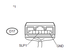
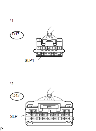
*1 |
Front view of wire harness connector (to Steering Lock ECU (Steering Lock Actuator Assembly)) |
|
*2 |
Front view of wire harness connector (to Power Management Control ECU) |
| OK | |
CHECK SMART KEY SYSTEM (for Start Function) |
| NG | |
REPAIR OR REPLACE HARNESS OR CONNECTOR |
 Steering Lock Motor Drive Power Circuit
DESCRIPTION
The steering lock ECU (steering lock actuator assembly) is connected to the power
management control ECU. The steering lock ECU (steering lock actuator assembly)
cannot activate the m ...
 Power Source Circuit
DESCRIPTION
This circuit supplies power source voltage from the battery to terminal B of
the steering lock ECU (steering lock actuator assembly). This is used as power source
for the CPU, motor, ...
Other materials about Toyota Venza:
Installation
INSTALLATION
PROCEDURE
1. INSTALL TRANSMISSION CONTROL CABLE ASSEMBLY
NOTICE:
Before installing the transmission control cable assembly, check that the park/neutral
position switch and the shift lever are in neutral.
(a) Pass the control cable from the ...
Rear Occupant Classification Sensor LH Circuit Malfunction (B1782)
DESCRIPTION
The rear occupant classification sensor LH circuit consists of the occupant classification
ECU and rear occupant classification sensor LH.
DTC B1782 is recorded when a malfunction is detected in the rear occupant classification
sensor LH circ ...
Removal
REMOVAL
PROCEDURE
1. PRECAUTION
CAUTION:
Be sure to read Precaution thoroughly before servicing (See page
).
2. DISCONNECT CABLE FROM NEGATIVE BATTERY TERMINAL
CAUTION:
Wait at least 90 seconds after disconnecting the cable from the negative (-)
bat ...

0.1165