Toyota Venza: System Diagram
SYSTEM DIAGRAM
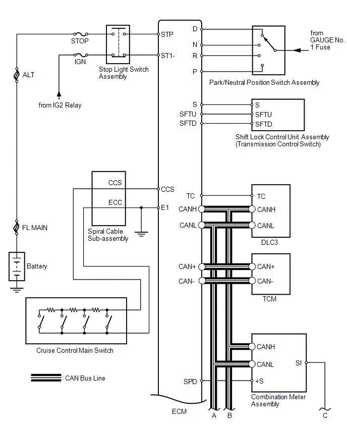
 Communication Table
|
Sender |
Receiver |
Signal |
Line |
|---|---|---|---|
|
ECM |
Combination Meter ECU |
|
CAN |
|
ECM |
TCM |
Shift up/down request signal |
CAN |
|
TCM |
ECM |
Shift up/down response signal |
CAN |
 Parts Location
PARTS LOCATION
ILLUSTRATION
ILLUSTRATION
...
 System Description
SYSTEM DESCRIPTION
1. CRUISE CONTROL SYSTEM
This system is controlled by the ECM, and is activated by the throttle position
sensor and motor. The ECM controls the following functions: ON-OFF, - SE ...
Other materials about Toyota Venza:
No Answer-Back
DESCRIPTION
In some cases, wireless door lock control functions are normal but the hazard
warning light and/or wireless door lock buzzer answer-back function(s) does not
operate. In such cases, the main body ECU (driver side junction block assembly)
haz ...
Data List / Active Test
DATA LIST / ACTIVE TEST
1. DATA LIST
HINT:
Using the Techstream to read the Data List allows the values or states of switches,
sensors, actuators and other items to be read without removing any parts. This non-intrusive
inspection can be very useful bec ...
Main Body Ecu
Components
COMPONENTS
ILLUSTRATION
Removal
REMOVAL
PROCEDURE
1. REMOVE UPPER INSTRUMENT PANEL
HINT:
Refer to the procedure up to Remove Upper Instrument Panel Sub-assembly (See
page ).
2. REMOVE MAIN BODY ECU (DRIVER SIDE JUNCTION BLOCK ASSEM ...

0.1397