Toyota Venza: Speed Sensor Rotor Faulty (C1237/37,C1275/75-C1278/78)
DESCRIPTION
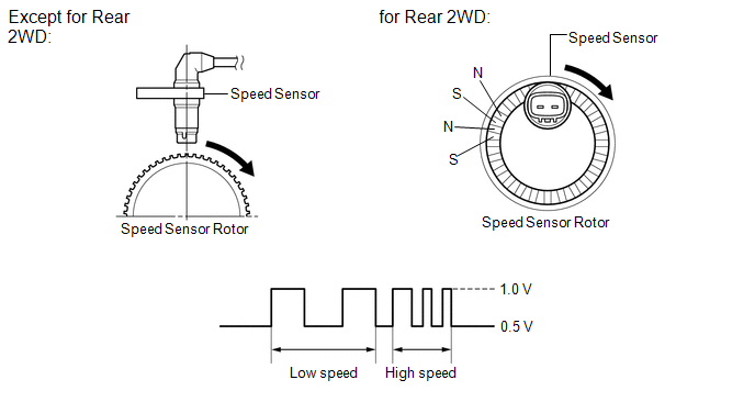
The skid control ECU measures the speed of each wheel by receiving signals from the speed sensor.
These signals are used for recognizing that all four wheels are operating properly.
Therefore, all wheel signals must be equal.
DTCs C1275/75 to C1278/78 will be cleared when the speed sensor sends a vehicle speed signal or when Test Mode ends. DTCs C1275/75 to C1278/78 are output only in Test Mode.
|
DTC Code |
DTC Detection Condition |
Trouble Area |
|---|---|---|
|
C1237/37 |
Any of the following is detected:
|
|
|
C1275/75 C1276/76 C1277/77 C1278/78 |
Detected only during Test Mode |
Speed sensor rotor |
HINT:
- DTC C1275/75 is for the front speed sensor RH.
- DTC C1276/76 is for the front speed sensor LH.
- DTC C1277/77 is for the rear speed sensor RH.
- DTC C1278/78 is for the rear speed sensor LH.
WIRING DIAGRAM
Refer to DTCs C0200/31, C0205/32, C0210/33, C0215/34, C1330/35, C1331/36, C1332/38
and C1333/39 (See page .gif) for front, or
for rear).
for front, or
for rear).
CAUTION / NOTICE / HINT
HINT:
When C0200/31, C0205/32, C0210/33, C0215/34, C1330/35, C1331/36, C1332/38 and/or
C1333/39 is output together with C1237/37, inspect and repair the trouble areas
indicated by C0200/31, C0205/32, C0210/33, C0215/34, C1330/35, C1331/36, C1332/38
and/or C1333/39 first (See page for front, or
for rear).
PROCEDURE
|
1. |
CHECK TIRES |
(a) Check the size and condition of all four wheels (See page
).
HINT:
The DTC is output when tire deformation or a difference in tire size is detected.
OK:
The diameter of all four tires and air pressure are the same.
|
Result |
Proceed to |
|---|---|
|
OK (except for rear 2WD) |
A |
|
OK (for rear 2WD) |
B |
|
NG |
C |
| B | .gif) |
GO TO STEP 9 |
| C | |
REPLACE TIRES SO THAT ALL FOUR TIRES ARE THE SAME SIZE |
|
.gif)
|
2. |
CHECK SPEED SENSOR AND SPEED SENSOR ROTOR |
(a) Remove the speed sensor and speed sensor rotor (See page
for front, or
for rear).
(b) Check the speed sensor tip and speed sensor rotor.
OK:
No scratches, oil, or foreign matter on the sensor tip and rotor.
NOTICE:
Check the speed sensor signal after cleaning or replacement (See page
).
| NG | |
CLEAN OR REPLACE SPEED SENSOR OR SPEED SENSOR ROTOR |
|
|
3. |
CHECK HARNESS AND CONNECTOR (SKID CONTROL ECU - SPEED SENSOR) |
(a) Install the speed sensor and speed sensor rotor.
(b) Make sure that there is no looseness at the locking part and the connecting part of the connectors.
(c) Disconnect the skid control ECU connector and the speed sensor connector.
(d) Measure the resistance according to the value(s) in the table below.
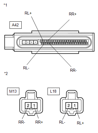
Standard Resistance:
for RH
|
Tester Connection |
Condition |
Specified Condition |
|---|---|---|
|
A42-9 (FR+) - A26-1 (FR+) |
Always |
Below 1 Ω |
|
A42-9 (FR+) - Body ground |
Always |
10 kΩ or higher |
|
A42-10 (FR-) - A26-2 (FR-) |
Always |
Below 1 Ω |
|
A42-10 (FR-) - Body ground |
Always |
10 kΩ or higher |
|
A42-8 (RR+) - M13-1 (RR+) |
Always |
Below 1 Ω |
|
A42-8 (RR+) - Body ground |
Always |
10 kΩ or higher |
|
A42-29 (RR-) - M13-2 (RR-) |
Always |
Below 1 Ω |
|
A42-29 (RR-) - Body ground |
Always |
10 kΩ or higher |
for LH
|
Tester Connection |
Condition |
Specified Condition |
|---|---|---|
|
A42-26 (FL+) - A27-1 (FL+) |
Always |
Below 1 Ω |
|
A42-26 (FL+) - Body ground |
Always |
10 kΩ or higher |
|
A42-5 (FL-) - A27-2 (FL-) |
Always |
Below 1 Ω |
|
A42-5 (FL-) - Body ground |
Always |
10 kΩ or higher |
|
A42-6 (RL+) - L18-1 (RL+) |
Always |
Below 1 Ω |
|
A42-6 (RL+) - Body ground |
Always |
10 kΩ or higher |
|
A42-27 (RL-) - L18-2 (RL-) |
Always |
Below 1 Ω |
|
A42-27 (RL-) - Body ground |
Always |
10 kΩ or higher |
|
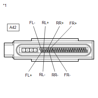
*1 |
Front view of wire harness connector (to Brake Actuator (Skid Control ECU)) |
|
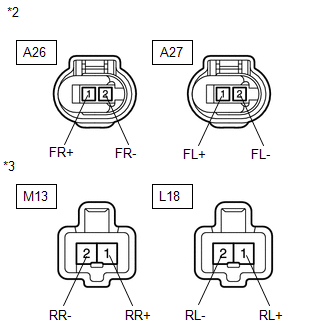
*2 |
Front view of wire harness connector (to Front Speed Sensor) |
|
*3 |
Front view of wire harness connector (to Rear Speed Sensor) |
| NG | |
REPAIR OR REPLACE HARNESS OR CONNECTOR |
|
|
4. |
RECONFIRM DTC |
(a) Reconnect the skid control ECU connector and the speed sensor connector.
(b) Clear the DTCs (See page ).
(c) Start the engine.
(d) Drive the vehicle at a speed of 20 km/h (12 mph) or more for at least 60 seconds.
(e) Check if the same DTC is recorded (See page
).
|
Result |
Proceed to |
|---|---|
|
DTC (C1237/37) is output |
A |
|
DTC (C1237/37) is not output |
B |
| B | |
CHECK FOR INTERMITTENT PROBLEMS |
|
|
5. |
REPLACE SPEED SENSOR |
(a) Turn the ignition switch off.
(b) Replace the speed sensor (See page for
front, or for rear).
NOTICE:
Check the speed sensor signal after replacement (See page
).
|
|
6. |
RECONFIRM DTC |
(a) Clear the DTCs (See page ).
(b) Start the engine.
(c) Drive the vehicle at a speed of 20 km/h (12 mph) or more for at least 60 seconds.
(d) Check if the same DTC is recorded (See page
).
|
Result |
Proceed to |
|---|---|
|
DTC (C1237/37) is output |
A |
|
DTC (C1237/37) is not output |
B |
| B | |
END |
|
|
7. |
REPLACE SPEED SENSOR ROTOR |
(a) Turn the ignition switch off.
(b) Remove the drive shaft assembly (See page
for front, or
for rear).
(c) Replace the drive outboard joint shaft assembly (speed sensor rotor) (See
page for front, or
for rear).
HINT:
If the speed sensor rotor needs to be replaced, replace it together with the drive outboard joint shaft assembly.
NOTICE:
Check the speed sensor signal after replacement (See page
).
|
|
8. |
RECONFIRM DTC |
(a) Install the drive shaft assembly.
(b) Clear the DTCs (See page ).
(c) Start the engine.
(d) Drive the vehicle at a speed of 20 km/h (12 mph) or more for at least 60 seconds.
(e) Check if the same DTC is recorded (See page
).
|
Result |
Proceed to |
|---|---|
|
DTC (C1237/37) is output |
A |
|
DTC (C1237/37) is not output |
B |
| A | |
REPLACE BRAKE ACTUATOR ASSEMBLY |
| B | |
END |
|
9. |
CHECK HARNESS AND CONNECTOR (SKID CONTROL SENSOR WIRE) |
|
(a) Make sure that there is no looseness at the locking part and the connecting part of the connectors. |
|
(b) Disconnect the skid control sensor wire.
(c) Measure the resistance according to the value(s) in the table below.
Standard Resistance:
for RH
|
Tester Connection |
Condition |
Specified Condition |
|---|---|---|
|
M13 ("A"-2) - M13 ("B"-1) |
Always |
Below 1 Ω |
|
M13 ("A"-2) - M13 ("B"-2) |
Always |
10 kΩ or higher |
|
M13 ("A"-2) - Body ground |
Always |
10 kΩ or higher |
|
M13 ("A"-1) - M13 ("B"-2) |
Always |
Below 1 Ω |
|
M13 ("A"-1) - M13 ("B"-1) |
Always |
10 kΩ or higher |
|
M13 ("A"-1) - Body ground |
Always |
10 kΩ or higher |
for LH
|
Tester Connection |
Condition |
Specified Condition |
|---|---|---|
|
L18 ("A"-2) - L18 ("B"-1) |
Always |
Below 1 Ω |
|
L18 ("A"-2) - L18 ("B"-2) |
Always |
10 kΩ or higher |
|
L18 ("A"-2) - Body ground |
Always |
10 kΩ or higher |
|
L18 ("A"-1) - L18 ("B"-2) |
Always |
Below 1 Ω |
|
L18 ("A"-1) - L18 ("B"-1) |
Always |
10 kΩ or higher |
|
L18 ("A"-1) - Body ground |
Always |
10 kΩ or higher |
|
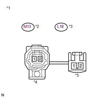
*1 |
Front view of skid control sensor wire |
|
*2 |
for RH |
|
*3 |
for LH |
|
*4 |
Front view of wire harness connector (to Sensor Side Connector "A") |
|
*5 |
Front view of wire harness connector (to Vehicle Side Connector "B") |
NOTICE:
Check the speed sensor signal after replacement (See page
).
| NG | |
REPLACE SKID CONTROL SENSOR WIRE |
|
|
10. |
CHECK HARNESS AND CONNECTOR (SKID CONTROL ECU - REAR SPEED SENSOR) |
|
(a) Reconnect the skid control sensor wire. |
|
(b) Make sure that there is no looseness at the locking part and the connecting part of the connectors.
(c) Disconnect the skid control ECU connector and the rear speed sensor connector.
(d) Measure the resistance according to the value(s) in the table below.
Standard Resistance:
for RH
|
Tester Connection |
Condition |
Specified Condition |
|---|---|---|
|
A42-8 (RR+) - M13-1 (RR+) |
Always |
Below 1 Ω |
|
A42-8 (RR+) - Body ground |
Always |
10 kΩ or higher |
|
A42-29 (RR-) - M13-2 (RR-) |
Always |
Below 1 Ω |
|
A42-29 (RR-) - Body ground |
Always |
10 kΩ or higher |
for LH
|
Tester Connection |
Condition |
Specified Condition |
|---|---|---|
|
A42-6 (RL+) - L18-1 (RL+) |
Always |
Below 1 Ω |
|
A42-6 (RL+) - Body ground |
Always |
10 kΩ or higher |
|
A42-27 (RL-) - L18-2 (RL-) |
Always |
Below 1 Ω |
|
A42-27 (RL-) - Body ground |
Always |
10 kΩ or higher |
|
*1 |
Front view of wire harness connector (to Brake Actuator (Skid Control ECU)) |
|
*2 |
Front view of wire harness connector (to Rear Speed Sensor) |
| NG | |
REPAIR OR REPLACE HARNESS OR CONNECTOR |
|
|
11. |
RECONFIRM DTC |
(a) Reconnect the skid control ECU connector and the rear speed sensor connector.
(b) Clear the DTCs (See page ).
(c) Start the engine.
(d) Drive the vehicle at a speed of 20 km/h (12 mph) or more for at least 60 seconds.
(e) Check if the same DTC is recorded (See page
).
|
Result |
Proceed to |
|---|---|
|
DTC (C1237/37) is output |
A |
|
DTC (C1237/37) is not output |
B |
| B | |
CHECK FOR INTERMITTENT PROBLEMS |
|
|
12. |
REPLACE REAR SPEED SENSOR AND REAR SPEED SENSOR ROTOR |
(a) Turn the ignition switch off.
(b) Replace the rear speed sensor and the rear axle hub and bearing assembly
(rear speed sensor rotor) (See page ).
HINT:
The rear speed sensor rotor is incorporated into the rear axle hub and bearing assembly.
If the rear speed sensor rotor needs to be replaced, replace it together with the rear axle hub and bearing assembly with rear speed sensor.
NOTICE:
Check the speed sensor signal after replacement (See page
).
|
|
13. |
RECONFIRM DTC |
(a) Clear the DTCs (See page ).
(b) Start the engine.
(c) Drive the vehicle at a speed of 20 km/h (12 mph) or more for at least 60 seconds.
(d) Check if the same DTC is recorded (See page
).
|
Result |
Proceed to |
|---|---|
|
DTC (C1237/37) is output |
A |
|
DTC (C1237/37) is not output |
B |
| A | |
REPLACE BRAKE ACTUATOR ASSEMBLY |
| B | |
END |
 Master Cylinder Pressure Sensor Malfunction (C1246/46,C1281/81)
DESCRIPTION
Master cylinder pressure sensor is connected to the skid control ECU in the brake
actuator assembly.
DTC C1281/81 will be cleared when the master cylinder pressure sensor sends a
mas ...
 Low Battery Positive Voltage or Abnormally High Battery Positive Voltage (C1241/41)
DESCRIPTION
If a malfunction is detected in the power supply circuit, the skid control ECU
(housed in the actuator assembly) stores this DTC and the fail-safe function prohibits
ABS operation.
T ...
Other materials about Toyota Venza:
Entry Answer-back Buzzer does not Sound
DESCRIPTION
The smart key system uses the wireless door lock buzzer to perform various vehicle
exterior warnings. When the conditions for each warning are met, the certification
ECU (smart key ECU assembly) sends a buzzer request signal to the main body E ...
Readiness Monitor Drive Pattern
READINESS MONITOR DRIVE PATTERN
1. PURPOSE OF READINESS TESTS
The On-Board Diagnostic (OBD II) system is designed to monitor the performance
of emission related components, and indicate any detected abnormalities
using DTCs (Diagnostic Trouble ...
ABS Control System Malfunction (43)
DESCRIPTION
This DTC is output when the VSC system detects a malfunction in the ABS control
system.
DTC Code
DTC Detection Condition
Trouble Area
43
Malfunction in the ABS control system.
...

0.1835