Toyota Venza: Removal
REMOVAL
PROCEDURE
1. REMOVE WINDSHIELD WIPER MOTOR AND LINK
(a) Remove the windshield wiper motor and link (See page
.gif) ).
).
2. REMOVE OUTER COWL TOP PANEL SUB-ASSEMBLY
3. REMOVE COOL AIR INTAKE DUCT SEAL
4. REMOVE NO. 1 ENGINE COVER SUB-ASSEMBLY
5. DISCONNECT CABLE FROM NEGATIVE BATTERY TERMINAL
NOTICE:
When disconnecting the cable, some systems need to be initialized after the cable
is reconnected (See page ).
6. REMOVE NO. 1 VACUUM SWITCHING VALVE ASSEMBLY
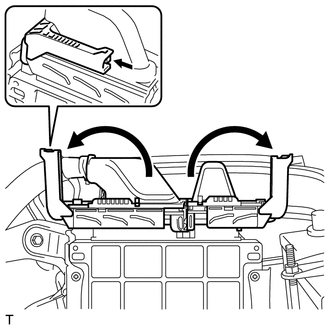
7. REMOVE AIR CLEANER CAP SUB-ASSEMBLY
8. REMOVE AIR CLEANER FILTER ELEMENT SUB-ASSEMBLY
9. REMOVE AIR CLEANER CASE SUB-ASSEMBLY
10. REMOVE AIR CLEANER BRACKET
|
(a) Remove the 2 bolts and air cleaner bracket. |
|
.png)
11. REMOVE ECM
|
(a) Separate the 3 wire harness clamps. |
|
.png)
|
(b) Raise the 2 levers while pushing the locks on the levers, and disconnect the 2 ECM connectors. NOTICE: After disconnecting each connector, make sure that dirt, water or other foreign matter does not contact the connecting part of the connector. |
|
|
(c) Remove the 3 bolts and the ECM with bracket. |
|
.png)
|
(d) Remove the 5 screws and the ECM bracket. |
|
.png)
 Installation
INSTALLATION
PROCEDURE
1. INSTALL ECM
(a) Install the bracket to the ECM with the 5 screws.
(b) Install the ECM with the 3 bolt ...

Other materials about Toyota Venza:
Camshaft Position "A" Actuator Circuit (Bank 1) (P0010)
DESCRIPTION
The Variable Valve Timing (VVT) system adjusts the intake valve timing to improve
driveability. The engine oil pressure turns the VVT controller to adjust the valve
timing.
The camshaft timing oil control valve assembly is a solenoid valve an ...
Removal
REMOVAL
PROCEDURE
1. REMOVE REAR DOOR SCUFF PLATE
2. DISCONNECT REAR DOOR OPENING TRIM WEATHERSTRIP
3. REMOVE TONNEAU COVER ASSEMBLY (w/ Tonneau Cover)
4. REMOVE DECK BOARD ASSEMBLY
5. REMOVE NO. 3 DECK BOARD SUB-ASSEMBLY
6. REMOVE DECK S ...
Inspection
INSPECTION
PROCEDURE
1. INSPECT TIE ROD ASSEMBLY LH
(a) Secure the tie rod assembly LH in a vise.
(b) Install the nut to the stud bolt.
(c) Flip the ball joint back and forth 5 times.
(d) Set a to ...

0.1389