Toyota Venza: Low Battery Positive Voltage or Abnormally High Battery Positive Voltage (C1241/41)
DESCRIPTION
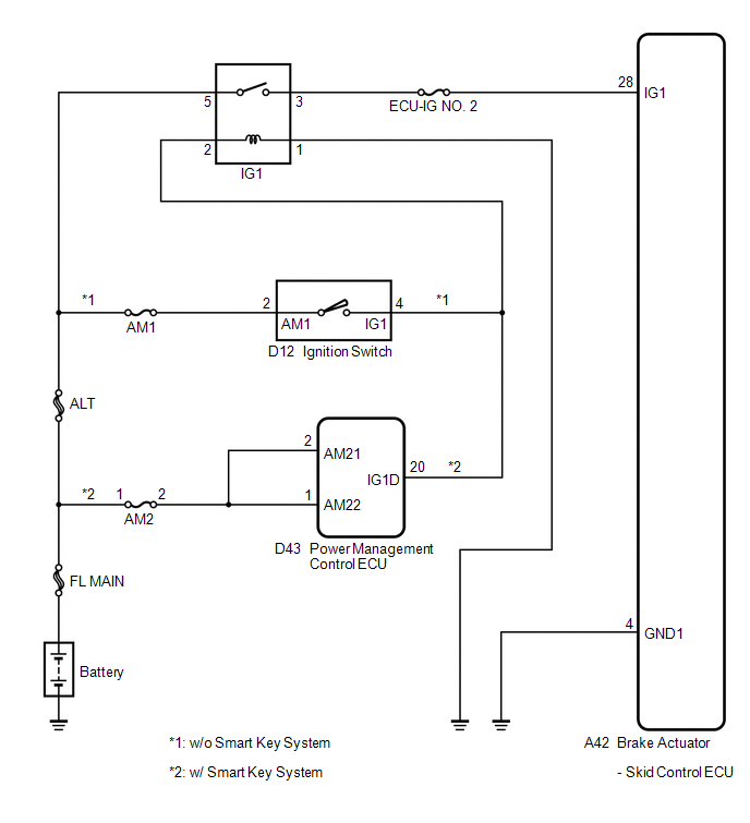
If a malfunction is detected in the power supply circuit, the skid control ECU (housed in the actuator assembly) stores this DTC and the fail-safe function prohibits ABS operation.
This DTC is stored when the IG1 terminal voltage deviates from the DTC detection condition due to a malfunction in the power supply or charging circuit such as the battery or alternator circuit, etc.
The DTC is cancelled when the IG1 terminal voltage returns to normal.
|
DTC Code |
DTC Detection Condition |
Trouble Area |
|---|---|---|
|
C1241/41 |
Any of the following is detected:
|
|
WIRING DIAGRAM
PROCEDURE
|
1. |
INSPECT ECU-IG NO. 2 FUSE |
|
(a) Remove the ECU-IG NO. 2 fuse from the main body ECU (driver side junction block). |
|
(b) Measure the resistance according to the value(s) in the table below.
Standard Resistance:
|
Tester Connection |
Condition |
Specified Condition |
|---|---|---|
|
ECU-IG NO. 2 (7.5 A) fuse |
Always |
Below 1 Ω |
|
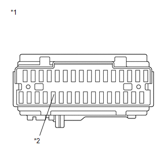
*1 |
Main Body ECU (Driver Side Junction Block) |
|
*2 |
ECU-IG NO. 2 Fuse |
| NG | .gif) |
REPLACE ECU-IG NO. 2 FUSE |
|
.gif)
|
2. |
CHECK BATTERY |
(a) Install the ECU-IG NO. 2 fuse.
(b) Check the battery voltage.
Standard Voltage:
11 to 14 V
|
Result |
Proceed to |
|---|---|
|
OK |
A |
|
NG (for 2GR-FE) |
B |
|
NG (for 1AR-FE) |
C |
| B | |
CHECK OR REPLACE CHARGING SYSTEM OR BATTERY (for 2GR-FE) |
| C | |
CHECK OR REPLACE CHARGING SYSTEM OR BATTERY (for 1AR-FE) |
|
|
3. |
INSPECT SKID CONTROL ECU (IG1 TERMINAL) |
|
(a) Make sure that there is no looseness at the locking part and the connecting part of the connector. |
|
(b) Disconnect the skid control ECU connector.
(c) Turn the ignition switch to ON.
(d) Measure the voltage according to the value(s) in the table below.
Standard Voltage:
|
Tester Connection |
Switch Condition |
Specified Condition |
|---|---|---|
|
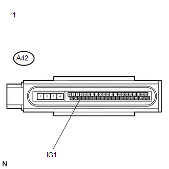
A42-28 (IG1) - Body ground |
Ignition switch ON |
11 to 14 V |
|
*1 |
Front view of wire harness connector (to Brake Actuator (Skid Control ECU)) |
| NG | |
REPAIR OR REPLACE HARNESS OR CONNECTOR (IG1 CIRCUIT) |
|
|
4. |
INSPECT SKID CONTROL ECU (GND1 TERMINAL) |
|
(a) Turn the ignition switch off. |
|
(b) Measure the resistance according to the value(s) in the table below.
Standard Resistance:
|
Tester Connection |
Condition |
Specified Condition |
|---|---|---|
|
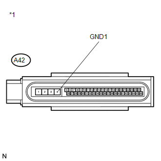
A42-4 (GND1) - Body ground |
Always |
Below 1 Ω |
|
*1 |
Front view of wire harness connector (to Brake Actuator (Skid Control ECU)) |
| NG | |
REPAIR OR REPLACE HARNESS OR CONNECTOR (GND1 CIRCUIT) |
|
|
5. |
RECONFIRM DTC |
(a) Reconnect the skid control ECU connector.
(b) Clear the DTCs (See page .gif) ).
).
(c) Start the engine.
(d) Perform a road test.
(e) Check if the same DTC is recorded (See page
).
|
Result |
Proceed to |
|---|---|
|
DTC (C1241/41) is not output |
A |
|
DTC (C1241/41) is output |
B |
HINT:
If troubleshooting has been carried out according to Problem Symptoms Table,
refer back to the table and proceed to the next step (See page
).
| A | |
CHECK FOR INTERMITTENT PROBLEMS |
| B | |
REPLACE BRAKE ACTUATOR ASSEMBLY |
 Speed Sensor Rotor Faulty (C1237/37,C1275/75-C1278/78)
DESCRIPTION
The skid control ECU measures the speed of each wheel by receiving signals from
the speed sensor.
These signals are used for recognizing that all four wheels are operating properly.
T ...
 Steering Angle Sensor Circuit Malfunction (C1231/31)
DESCRIPTION
The steering angle sensor signal is sent to the skid control ECU via the CAN
communication system. When there is a malfunction in the CAN communication system,
it will be detected by ...
Other materials about Toyota Venza:
Installation
INSTALLATION
PROCEDURE
1. INSTALL REAR SEAT INNER BELT ASSEMBLY LH
(a) Install the rear seat inner belt assembly LH with the bolt.
Text in Illustration
*1
Protruding Part
Torque:
42 NÂ ...
Reassembly
REASSEMBLY
PROCEDURE
1. INSTALL REAR CONSOLE ARMREST ASSEMBLY
(a) Temporarily install the rear console armrest assembly.
(b) Push in the box door hinge shafts by hand as far as possible.
HINT:
The illustration is for the LH sid ...
Replacement
REPLACEMENT
CAUTION / NOTICE / HINT
HINT:
Use the same procedure for the RH side and LH side.
The procedure listed below is for the LH side.
PROCEDURE
1. DRAIN DIFFERENTIAL OIL
2. REMOVE REAR WHEEL
3. REMOVE CENTER EXHAUST PIPE ASSE ...

0.113