Toyota Venza: TC and CG Terminal Circuit
DESCRIPTION
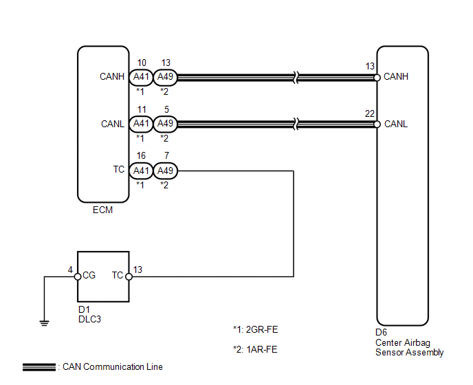
DTC output mode is set by connecting terminals TC and CG of the DLC3.
DTCs are displayed by blinking of the SRS warning light.
HINT:
- When each warning light stays blinking, a ground short in the wiring of terminal TC of the DLC3 or an internal ground short in each ECU is suspected.
- A DTC output mode signal is transmitted through the CAN communication system to each ECU including the center airbag sensor assembly. Thus when all systems do not enter DTC output mode, there may be an ECM malfunction.
WIRING DIAGRAM
PROCEDURE
|
1. |
CHECK WIRE HARNESS (TC OF DLC3 - TC OF ECM) |
|
(a) Turn the ignition switch off. |
|
(b) Disconnect the connector from the ECM.
(c) Measure the resistance according to the value(s) in the table below.
Standard Resistance:
for 2GR-FE
|
Tester Connection |
Condition |
Specified Condition |
|---|---|---|
|
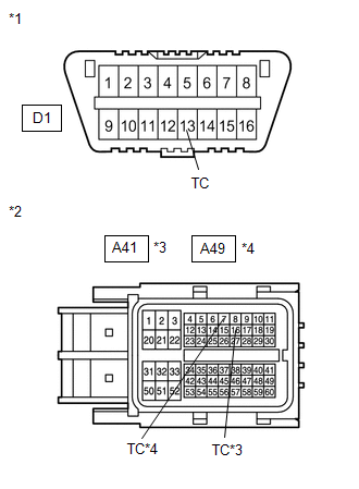
D1-13 (TC) - A41-16 (TC) |
Always |
Below 1 Ω |
for 1AR-FE
|
Tester Connection |
Condition |
Specified Condition |
|---|---|---|
|
D1-13 (TC) - A49-7 (TC) |
Always |
Below 1 Ω |
|
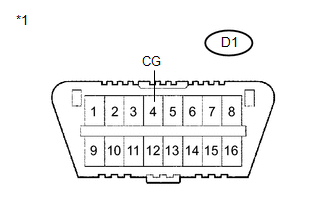
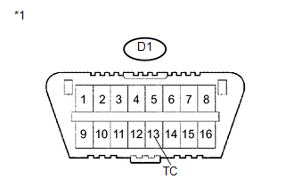
*1 |
Front view of wire harness connector (to DLC3) |
|
*2 |
Front view of wire harness connector (to ECM) |
|
*3 |
for 2GR-FE |
|
*4 |
for 1AR-FE |
| NG | .gif) |
REPLACE WIRE HARNESS |
|
.gif)
|
2. |
CHECK WIRE HARNESS (CG OF DLC3 - BODY GROUND) |
|
(a) Measure the resistance according to the value(s) in the table below. Standard Resistance:
|
|
| NG | |
REPLACE WIRE HARNESS |
|
|
3. |
CHECK WIRE HARNESS (TC OF DLC3 - BODY GROUND) |
|
(a) Measure the resistance according to the value(s) in the table below. Standard Resistance:
|
|
| OK | |
REPLACE CENTER AIRBAG SENSOR ASSEMBLY |
| NG | |
REPLACE WIRE HARNESS OR EACH ECU |
 SRS Warning Light does not Come ON
DESCRIPTION
The SRS warning light is located on the combination meter assembly.
When the SRS is normal, the SRS warning light comes on for approximately 6 seconds
after the ignition switch is turn ...

Other materials about Toyota Venza:
Inspection
INSPECTION
PROCEDURE
1. INSPECT GENERATOR PULLEY WITH CLUTCH
(a) Hold the center of the pulley, and confirm that the outer ring turns
counterclockwise and does not turn clockwise.
Text in Illustration
*1
...
Inspection
INSPECTION
PROCEDURE
1. INSPECT PARKING BRAKE SWITCH ASSEMBLY
(a) Measure the resistance according to the value(s) in the table below.
Standard Resistance:
Tester Connection
Switch Condition
...
Unmatched Encryption Code (B2794)
DESCRIPTION
This DTC is stored when a key with an incomplete key code is inserted into the
ignition key cylinder.
DTC No.
DTC Detection Condition
Trouble Area
B2794
Key with incomplete key code i ...

0.1372