Toyota Venza: System Diagram
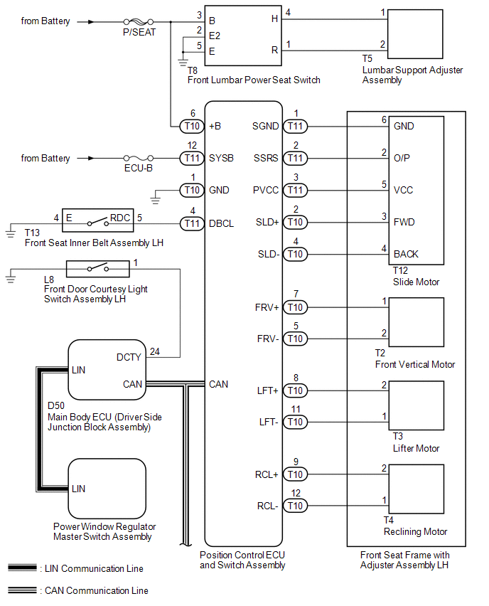
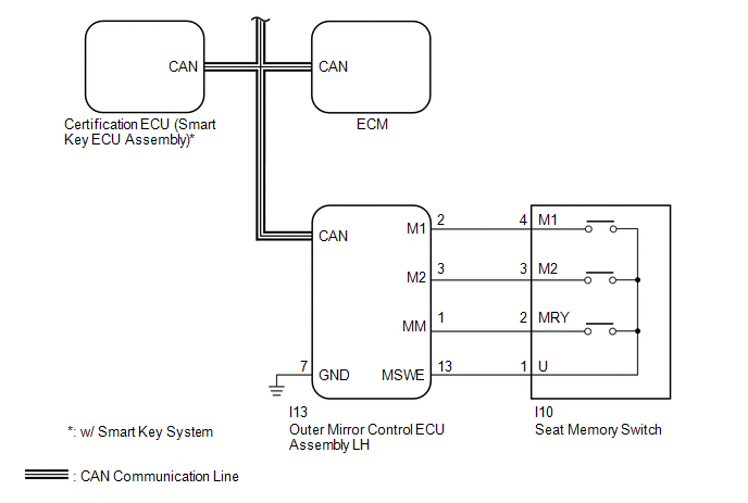
SYSTEM DIAGRAM
 Communication Table
|
Sender |
Receiver |
Signal |
Line |
|---|---|---|---|
|
ECM |
Main Body ECU (Driver Side Junction Block Assembly) |
|
CAN |
|
Outer Mirror Control ECU Assembly LH |
Main Body ECU (Driver Side Junction Block Assembly) |
|
CAN |
|
Main Body ECU (Driver Side Junction Block Assembly) |
Position Control ECU and Switch Assembly |
|
CAN |
|
Certification ECU (Smart Key ECU Assembly)* |
Main Body ECU (Driver Side Junction Block Assembly) |
|
CAN |
|
Position Control ECU and Switch Assembly |
Main Body ECU (Driver Side Junction Block Assembly) |
|
CAN |
- *: w/ Smart Key System
 System Description
SYSTEM DESCRIPTION
1. FRONT POWER SEAT CONTROL SYSTEM DESCRIPTION
The driver seat is equipped with slide, reclining, lifter, front vertical,
and lumbar support adjustment functions.
T ...
 How To Proceed With Troubleshooting
CAUTION / NOTICE / HINT
HINT:
Use the following procedure to troubleshoot the front power seat control
system (w/ Memory).
*: Use the Techstream.
PROCEDURE
1.
...
Other materials about Toyota Venza:
Reassembly
REASSEMBLY
PROCEDURE
1. INSTALL NO. 14 ROOF SILENCER PAD
(a) Align the markings on the roof headlining assembly with the No. 14 roof silencer
pad and install the silencer pad using hot-melt glue as shown in the illustration.
2. INSTALL NO. 1 ROOF WIRE ...
Precaution
PRECAUTION
1. PRECAUTION FOR DISCONNECTING THE BATTERY CABLE
NOTICE:
When disconnecting the cable from the negative (-) battery terminal, initialize
the following systems after the cable is reconnected:
System
See Procedure
...
Ignition Switch
Components
COMPONENTS
ILLUSTRATION
Removal
REMOVAL
PROCEDURE
1. REMOVE LOWER STEERING COLUMN COVER
2. REMOVE UPPER STEERING COLUMN COVER
3. REMOVE IGNITION SWITCH
(a) Remove the 2 screws and ignition switch.
...

0.136