Toyota Venza: Security Horn Circuit
DESCRIPTION
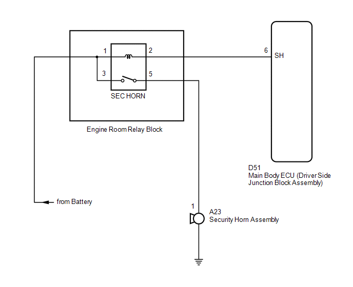
When the theft deterrent system is switched from the armed state to the alarm sounding state, the main body ECU (driver side junction block assembly) controls the security horn.
WIRING DIAGRAM
PROCEDURE
|
1. |
PERFORM ACTIVE TEST USING TECHSTREAM |
(a) Connect the Techstream to the DLC3.
(b) Turn the engine switch on (IG).
(c) Turn the Techstream on.
(d) Select the item below in the Active Test and then check that the security horn assembly operates.
Body|
Tester Display |
Test Part |
Control Range |
Diagnostic Note |
|---|---|---|---|
|
Security Horn |
Security horn |
ON/OFF |
- |
OK:
The security horn assembly sounds and stops correctly when operated through the Techstream.
| OK | .gif) |
PROCEED TO NEXT SUSPECTED AREA SHOWN IN PROBLEM SYMPTOMS TABLE |
|
.gif)
|
2. |
INSPECT SECURITY HORN ASSEMBLY |
|
(a) Remove the security horn assembly (See page
|
|
.gif) ).
)..png)
(b) Check the operation of the security horn assembly.
OK:
|
Measurement Condition |
Specified Condition |
|---|---|
|
Battery positive (+) → Terminal 1 |
Horn sounds |
|
Battery negative (-) → Horn body |
| NG | |
REPLACE SECURITY HORN ASSEMBLY |
|
|
3. |
INSPECT SEC HORN RELAY |
|
(a) Remove the SEC HORN relay from the engine room relay block. |
|

(b) Measure the resistance according to the value(s) in the table below.
Standard Resistance:
|
Tester Connection |
Condition |
Specified Condition |
|---|---|---|
|
3 - 5 |
Battery voltage applied to terminals 1 and 2 |
Below 1 Ω |
|
3 - 5 |
Battery voltage not applied between terminals 1 and 2 |
10 kΩ or higher |
| NG | |
REPLACE SEC HORN RELAY |
|
|
4. |
CHECK HARNESS AND CONNECTOR (SEC HORN RELAY POWER SOURCE) |
|
(a) Measure the voltage according to the value(s) in the table below. Standard Voltage:
|
|
| NG | |
REPAIR OR REPLACE HARNESS OR CONNECTOR |
|
|
5. |
CHECK HARNESS AND CONNECTOR (SEC HORN RELAY - MAIN BODY ECU) |
|
(a) Disconnect the D51 main body ECU (driver side junction block assembly) connector. |
|
(b) Measure the resistance on the relay block side according to the value(s) in the table below.
Standard Resistance:
|
Tester Connection |
Condition |
Specified Condition |
|---|---|---|
|
Engine room relay block SEC HORN relay terminal 1 - D51-6 (SH) |
Always |
Below 1 Ω |
|
Engine room relay block SEC HORN relay terminal 1 - Body ground |
Always |
10 kΩ or higher |
|
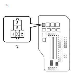
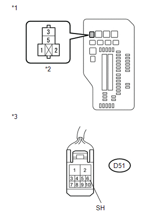
*1 |
Engine Room Relay Block |
|
*2 |
SEC HORN Relay Terminal |
|
*3 |
Front view of wire harness connector (to Main Body ECU (Driver Side Junction Block Assembly)) |
| NG | |
REPAIR OR REPLACE HARNESS OR CONNECTOR |
|
|
6. |
CHECK HARNESS AND CONNECTOR (SEC HORN RELAY POWER SOURCE) |
|
(a) Measure the voltage according to the value(s) in the table below. Standard Voltage:
|
|
| NG | |
REPAIR OR REPLACE HARNESS OR CONNECTOR |
|
|
7. |
CHECK HARNESS AND CONNECTOR (SEC HORN RELAY - SECURITY HORN ASSEMBLY) |
|
(a) Disconnect the A23 security horn assembly connector. |
|
(b) Measure the resistance according to the value(s) in the table below.
Standard Resistance:
|
Tester Connection |
Condition |
Specified Condition |
|---|---|---|
|
Engine room relay block SEC HORN relay terminal 5 - A23-1 |
Always |
Below 1 Ω |
|
Engine room relay block SEC HORN relay terminal 5 - Body ground |
Always |
10 kΩ or higher |
|
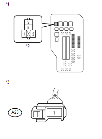
*1 |
Engine Room Relay Block |
|
*2 |
SEC HORN Relay Terminal |
|
*3 |
Front view of wire harness connector (to Security Horn Assembly) |
| OK | |
REPLACE MAIN BODY ECU (DRIVER SIDE JUNCTION BLOCK ASSEMBLY) |
| NG | |
REPAIR OR REPLACE HARNESS OR CONNECTOR |
 Horn Circuit
DESCRIPTION
When the theft deterrent system is switched from the armed state to the alarm
sounding state, the main body ECU (driver side junction block assembly) transmits
a signal to cause the h ...
 Security Indicator Light Circuit
DESCRIPTION
Even when the theft deterrent system is in the disarmed state, the security indicator
blinks due to a signal output from the immobiliser system. The security indicator
blinks continuo ...
Other materials about Toyota Venza:
Cruise SET Indicator Light Circuit
DESCRIPTION
The ECM detects a cruise control switch signal and sends it to the combination
meter assembly through CAN. Then the SET indicator light comes on.
The SET indicator light circuit uses CAN for communication. If there
is a malfunct ...
Removal
REMOVAL
PROCEDURE
1. PRECAUTION
CAUTION:
Be sure to read Precaution thoroughly before servicing (See page
).
2. TURN FRONT WHEELS TO FACE STRAIGHT AHEAD
3. DISCONNECT CABLE FROM NEGATIVE BATTERY TERMINAL
CAUTION:
Wait at least 90 seconds after discon ...
Jam Protection Function does not Operate
DESCRIPTION
This symptom may occur for any of the windows.
The jam protection function operates within a specified range during the manual
up or auto up operation.
CAUTION / NOTICE / HINT
NOTICE:
The power window control system uses a multiplex ...

0.136