Toyota Venza: Terminals Of Ecu
TERMINALS OF ECU
1. TCM

HINT:
Each TCM terminal standard voltage is shown in the table below.
In the table, first follow the information under "Condition". Look under "Terminal No. (Symbol)" for the terminals to be inspected. The standard voltage between the terminals is shown under "Specified Condition".
Use the illustration above as a reference for the TCM terminals.
|
Terminal No. (Symbol) |
Wiring Color |
Terminal Description |
Condition |
Specified Condition |
|---|---|---|---|---|
|
B40-15 (R) - B40-8 (E1) |
G - B |
R shift position switch signal |
Ignition switch ON and shift lever in R |
11 to 14 V |
|
Ignition switch ON and shift lever in any position except R |
Below 1 V |
|||
|
B40-16 (D) - B40-8 (E1) |
LG - B |
D shift position switch signal |
Ignition switch ON and shift lever in D and S |
11 to 14 V |
|
Ignition switch ON and shift lever in any position except D and S |
Below 1 V |
|||
|
B40-12 (STP) - B40-8 (E1) |
P - B |
Stop light switch signal |
Brake pedal is depressed |
7.5 to 14 V |
|
Brake pedal is released |
Below 1.5 V |
|||
|
B40-11 (NSW) - B40-8 (E1) |
GR - B |
Park/neutral switch signal |
Ignition switch ON and shift lever in P or N |
Below 2 V |
|
Ignition switch ON and shift lever in any position except P or N |
11 to 14 V |
|||
|
B40-10 (STA) - B40-8 (E1) |
V - B |
Starter signal |
Cranking (shift lever in P or N, engine switch START) |
11 to 14 V |
|
Ignition switch ON and shift lever in any position except P or N |
Below 2 V |
|||
|
B40-3 (SPD) - B40-8 (E1) |
L - B |
Speed signal from combination meter |
Vehicle speed 20 km/h (12 mph) |
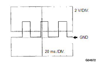
Pulse generation (see waveform 1) |
|
B40-1 (BATT) - B40-8 (E1) |
W-L - B |
Battery (for measuring battery voltage and for TCM memory) |
Always |
9 to 14 V |
|
B40-13 (IGSW) - B40-8 (E1) |
Y - B |
Ignition switch |
Ignition switch ON |
9 to 14 V |
|
B40-18 (+B) - B40-8 (E1) |
Y - B |
Power source of TCM |
Ignition switch ON |
9 to 14 V |
|
B40-6 (CAN+) - B40-8 (E1) |
R - B |
CAN communication line |
Ignition switch ON |
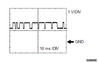
Pulse generation (see waveform 2) |
|
B40-7 (CAN-) - B40-8 (E1) |
W - B |
CAN communication line |
Ignition switch ON |
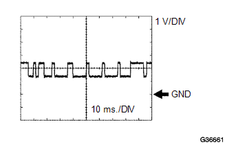
Pulse generation (see waveform 3) |
(a) Waveform 1
 Reference
|
Terminal |
SPD - E1 |
|
Tool setting |
2 V/DIV., 20 ms./DIV. |
|
Vehicle condition |
Vehicle speed 20 km/h (12 mph) |
(b) Waveform 2
 Reference
|
Terminal |
CAN+ - E1 |
|
Tool setting |
1 V/DIV., 10 ms./DIV. |
|
Vehicle condition |
Engine is stopped, ignition switch ON |
(c) Waveform 3
 Reference
|
Terminal |
CAN- - E1 |
|
Tool setting |
1 V/DIV., 10 ms./DIV. |
|
Vehicle condition |
Engine is stopped, ignition switch ON |
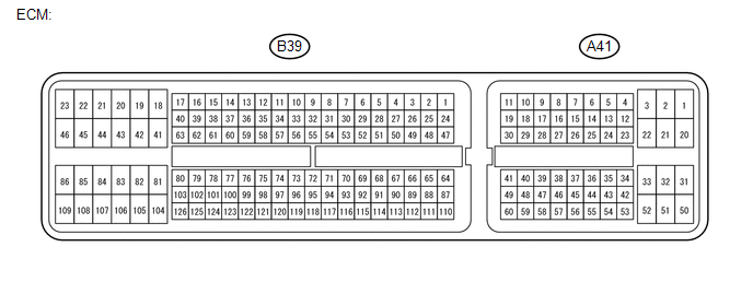
2. ECM
HINT:
Each ECM terminal standard voltage is shown in the table below.
In the table, first follow the information under "Condition". Look under "Terminal No. (Symbol)" for the terminals to be inspected. The standard voltage between the terminals is shown under "Specified Condition".
Use the illustration below as a reference for the ECM terminals.
|
Terminal No. (Symbol) |
Wiring Color |
Terminal Description |
Condition |
Specified Condition |
|---|---|---|---|---|
|
A41-25 (S) - B39-81 (E1) |
BE - W |
S shift position switch signal |
Ignition switch ON and shift lever in S |
11 to 14 V |
|
Ignition switch ON and shift lever in any position except S |
Below 1 V |
|||
|
A41-38 (SFTU) - B39-81 (E1) |
R - W |
Up shift switch signal |
Ignition switch ON and shift lever in S |
11 to 14 V |
|
Ignition switch ON and shift lever in "+" (Up shift) |
Below 1 V |
|||
|
A41-27 (SFTD) - B39-81 (E1) |
LG - W |
Down shift switch signal |
Ignition switch ON and shift lever in S |
11 to 14 V |
|
Ignition switch ON and shift lever in "-" (Down shift) |
Below 1 V |
 Diagnosis System
DIAGNOSIS SYSTEM
1. DESCRIPTION
(a) When troubleshooting On-Board Diagnostic (OBD II) vehicles, the vehicle must
be connected to the OBD II scan tool (complying with SAE J1987). Various data outpu ...
 Dtc Check / Clear
DTC CHECK / CLEAR
NOTICE:
When the diagnosis system is changed from normal mode to check mode or vice versa,
all DTCs and freeze frame data recorded in normal mode are cleared. Before changing
m ...
Other materials about Toyota Venza:
Starter Signal Circuit
DESCRIPTION
1. w/o Smart Key System
While the engine is being cranked, current flows from terminal ST1 of the ignition
switch assembly to the park/neutral position switch assembly and also flows to terminal
STA of the ECM (STA Signal).
2. w/ Smart Key S ...
Body
General Maintenance
GENERAL MAINTENANCE
PROCEDURE
1. TIGHTEN BOLTS AND NUTS ON CHASSIS AND BODY
(a) If necessary, tighten the bolts and nuts on the chassis parts listed below.
Front axle and suspension
Drivetrain
Rear axle and suspension ...
Installation
INSTALLATION
CAUTION / NOTICE / HINT
HINT:
Use the same procedure for the RH side and LH side.
The procedure listed below is for the LH side.
PROCEDURE
1. INSTALL FRONT AIRBAG SENSOR
(a) Check that the ignition switch is off.
(b) Check ...

0.1142