Toyota Venza: Rear Occupant Classification Sensor LH Circuit Malfunction (B1782)
DESCRIPTION
The rear occupant classification sensor LH circuit consists of the occupant classification ECU and rear occupant classification sensor LH.
DTC B1782 is recorded when a malfunction is detected in the rear occupant classification sensor LH circuit.
|
DTC No. |
DTC Detection Condition |
Trouble Area |
|---|---|---|
|
B1782 |
|
|
HINT:
When DTC B1650/32 is detected as a result of troubleshooting for the airbag system, check the DTCs stored in the occupant classification ECU. When DTC B1782 is output, perform troubleshooting for the DTC.
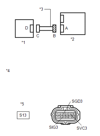
WIRING DIAGRAM
.png)
CAUTION / NOTICE / HINT
HINT:
- If troubleshooting (wire harness inspection) is difficult to perform, remove the front passenger seat installation bolts to see under the seat cushion.
- In the above case, hold the seat so that it does not fall down. Hold the seat only as necessary because holding the seat for a long period of time may cause seat rail deformation.
PROCEDURE
|
1. |
CHECK CONNECTORS |
(a) Turn the ignition switch off.
(b) Disconnect the cable from the negative (-) battery terminal.
(c) Check that the connectors are properly connected to the occupant classification ECU and rear occupant classification sensor LH.
OK:
The connectors are properly connected.
HINT:
If the connectors are not connected securely, reconnect the connectors and proceed to the next inspection.
(d) Disconnect the connectors from the occupant classification ECU and rear occupant classification sensor LH.
(e) Check that the terminals of connectors are not damaged.
OK:
The terminals are not deformed or damaged.
| NG | .gif) |
REPLACE FRONT SEAT WIRE RH |
|
.gif)
|
2. |
CHECK FRONT SEAT WIRE RH (SHORT TO B+) |
|
(a) Connect the cable to the negative (-) battery terminal. |
|
(b) Turn the ignition switch to ON.
(c) Measure the voltage according to the value(s) in the table below.
Standard Voltage:
|
Tester Connection |
Switch Condition |
Specified Condition |
|---|---|---|
|
S13-3 (SGD3) - Body ground |
Ignition switch ON |
Below 1 V |
|
S13-5 (SVC3) - Body ground |
Ignition switch ON |
Below 1 V |
|
S13-9 (SIG3) - Body ground |
Ignition switch ON |
Below 1 V |
|
*1 |
Rear Occupant Classification Sensor LH |
|
*2 |
Occupant Classification ECU |
|
*3 |
Front Seat Wire RH |
|
*4 |
Front view of wire harness connector (to Occupant Classification ECU) |
|
*5 |
Connector B |
| NG | |
REPLACE FRONT SEAT WIRE RH |
|
|
3. |
CHECK FRONT SEAT WIRE RH (OPEN) |
(a) Turn the ignition switch off.
(b) Disconnect the cable from the negative (-) battery terminal.
(c) Using SST, connect terminals 1 (SVC3) and 3 (SGD3), and connect terminals 2 (SIG3) and 3 (SGD3) of connector C.
NOTICE:
Do not forcibly insert SST into the terminals of the connector when connecting.
SST: 09843-18040
(d) Measure the resistance according to the value(s) in the table below.
Standard Resistance:
|
Tester Connection |
Condition |
Specified Condition |
|---|---|---|
|
S13-5 (SVC3) - S13-3 (SGD3) |
Always |
Below 1 Ω |
|
S13-9 (SIG3) - S13-3 (SGD3) |
Always |
Below 1 Ω |
|
*1 |
Rear Occupant Classification Sensor LH |
*2 |
Occupant Classification ECU |
|
*3 |
Front Seat Wire RH |
*4 |
Front view of wire harness connector (to Occupant Classification ECU) |
|
*5 |
Front view of wire harness connector (to Rear Occupant Classification Sensor LH) |
*6 |
Connector B |
|
*7 |
Connector C |
- |
- |
| NG | |
REPLACE FRONT SEAT WIRE RH |
|
|
4. |
CHECK FRONT SEAT WIRE RH (SHORT) |
|
(a) Disconnect SST from connector C. |
|
(b) Measure the resistance according to the value(s) in the table below.
Standard Resistance:
|
Tester Connection |
Condition |
Specified Condition |
|---|---|---|
|
S13-5 (SVC3) - S13-3 (SGD3) |
Always |
1 MΩ or higher |
|
S13-9 (SIG3) - S13-3 (SGD3) |
Always |
1 MΩ or higher |
|
S13-5 (SVC3) - S13-9 (SIG3) |
Always |
1 MΩ or higher |
|
*1 |
Rear Occupant Classification Sensor LH |
|
*2 |
Occupant Classification ECU |
|
*3 |
Front Seat Wire RH |
|
*4 |
Front view of wire harness connector (to Occupant Classification ECU) |
|
*5 |
Connector B |
| NG | |
REPLACE FRONT SEAT WIRE RH |
|
|
5. |
CHECK FRONT SEAT WIRE RH (SHORT TO GROUND) |
|
(a) Measure the resistance according to value(s) in the table below. Standard Resistance:
|
|
| NG | |
REPLACE FRONT SEAT WIRE RH |
|
|
6. |
CHECK DTC |
(a) Connect the connectors to the occupant classification ECU and rear occupant classification sensor LH.
(b) Connect the cable to the negative (-) battery terminal.
(c) Turn the ignition switch to ON.
(d) Clear the DTCs stored in the occupant classification ECU (See page
.gif) ).
).
(e) Clear the DTCs stored in the center airbag sensor assembly (See page
).
(f) Turn the ignition switch off.
(g) Turn the ignition switch to ON.
(h) Check for DTCs (See page ).
OK:
DTC B1782 is not output.
HINT:
Codes other than DTC B1782 may be output at this time, but they are not related to this check.
| OK | |
USE SIMULATION METHOD TO CHECK |
|
|
7. |
REPLACE OCCUPANT CLASSIFICATION ECU |
(a) Turn the ignition switch off.
(b) Disconnect the cable from the negative (-) battery terminal.
(c) Replace the occupant classification ECU (See page
).
HINT:
Perform the inspection using parts from a normal vehicle if possible.
|
|
8. |
PERFORM ZERO POINT CALIBRATION |
(a) Connect the cable to the negative (-) battery terminal.
(b) Connect the Techstream to the DLC3.
(c) Turn the ignition switch to ON.
(d) Using the Techstream, perform Zero Point Calibration (See page
).
OK:
"Zero Point Calibration is complete." is displayed.
| NG | |
GO TO STEP 11 |
|
|
9. |
PERFORM SENSITIVITY CHECK |
(a) Using the Techstream, perform Sensitivity Check (See page
).
Standard:
27 to 33 kg (59.5 to 72.8 lb)
| NG | |
GO TO STEP 11 |
|
|
10. |
CHECK DTC |
(a) Turn the ignition switch to ON.
(b) Clear the DTCs stored in the occupant classification ECU (See page
).
(c) Clear the DTCs stored in the center airbag sensor assembly (See page
).
(d) Turn the ignition switch off.
(e) Turn the ignition switch to ON.
(f) Check for DTCs (See page ).
OK:
DTC B1782 is not output.
HINT:
Codes other than DTC B1782 may be output at this time, but they are not related to this check.
| OK | |
END |
|
|
11. |
REPLACE FRONT SEAT FRAME WITH ADJUSTER ASSEMBLY RH |
(a) Turn the ignition switch off.
(b) Disconnect the cable from the negative (-) battery terminal.
(c) Replace the front seat frame with adjuster assembly RH (See page
for power seat or
for manual seat).
|
|
12. |
PERFORM ZERO POINT CALIBRATION |
(a) Connect the cable to the negative (-) battery terminal.
(b) Connect the Techstream to the DLC3.
(c) Turn the ignition switch to ON.
(d) Using the Techstream, perform Zero Point Calibration (See page
).
OK:
"Zero Point Calibration is complete." is displayed.
|
|
13. |
PERFORM SENSITIVITY CHECK |
(a) Using the Techstream, perform Sensitivity Check (See page
).
Standard:
27 to 33 kg (59.5 to 72.8 lb)
| NEXT | |
END |
 Front Occupant Classification Sensor LH Collision Detection (B1785)
DESCRIPTION
DTC B1785 is output when the occupant classification ECU receives a collision
detection signal sent by the front occupant classification sensor LH if an accident
occurs.
DTC B1785 is ...
 Rear Occupant Classification Sensor RH Circuit Malfunction (B1783)
DESCRIPTION
The rear occupant classification sensor RH circuit consists of the occupant classification
ECU and rear occupant classification sensor RH.
DTC B1783 is recorded when a malfunction is d ...
Other materials about Toyota Venza:
If your vehicle overheats
The following may indicate that your vehicle is overheating.
• The engine coolant temperature gauge reaches the maximum, or a loss of
engine power is experienced. (For example, the vehicle speed does not increase.)
• Steam comes out from under the hood ...
Operation Check
OPERATION CHECK
1. CHECK AUTO OPERATION
NOTICE:
Make sure that initialization is completed before inspection (See page
).
HINT:
When pressing the switch for 0.3 seconds or less, the roof glass moves but auto
operation does not operate.
(a) Turn the i ...
Precaution
PRECAUTION
1. PRECAUTION FOR DISCONNECTING CABLE FROM NEGATIVE BATTERY TERMINAL
NOTICE:
When disconnecting the cable from the negative (-) battery terminal, initialize
the following system after the cable is reconnected.
System Name
...

0.1352