Toyota Venza: Horn Circuit
DESCRIPTION
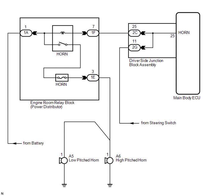
When the theft deterrent system is switched from the armed state to the alarm sounding state, the main body ECU (driver side junction block assembly) transmits a signal to cause the horn to sound at intervals of 0.4 seconds.
WIRING DIAGRAM
PROCEDURE
|
1. |
INSPECT HORNS |
(a) Press the horn switch and check if the horns sound.
|
Result |
Proceed to |
|---|---|
|
Horns sound |
A |
|
Horns do not sound |
B |
| B | .gif) |
GO TO HORN SYSTEM |
|
.gif)
|
2. |
PERFORM ACTIVE TEST USING TECHSTREAM |
(a) Connect the Techstream to the DLC3.
(b) Turn the engine switch on (IG).
(c) Turn the Techstream on.
(d) Select the item below in the Active Test and then check that the horns operate.
Main Body|
Tester Display |
Test Part |
Control Range |
Diagnostic Note |
|---|---|---|---|
|
Vehicle Horn |
Vehicle horns |
ON / OFF |
- |
OK:
The vehicle horns sound and stop correctly when operated through the Techstream.
| OK | |
PROCEED TO NEXT SUSPECTED AREA SHOWN IN PROBLEM SYMPTOMS TABLE |
| NG | |
REPLACE MAIN BODY ECU (DRIVER SIDE JUNCTION BLOCK ASSEMBLY) |
 Engine Hood Courtesy Switch Circuit
DESCRIPTION
The security courtesy switch is installed together with the hood lock. This switch
turns off when the engine hood is opened and turns on when the engine hood is closed.
WIRING DIAGRAM
...
 Security Horn Circuit
DESCRIPTION
When the theft deterrent system is switched from the armed state to the alarm
sounding state, the main body ECU (driver side junction block assembly) controls
the security horn.
WIRI ...
Other materials about Toyota Venza:
Components
COMPONENTS
ILLUSTRATION
ILLUSTRATION
ILLUSTRATION
ILLUSTRATION
ILLUSTRATION
ILLUSTRATION
ILLUSTRATION
...
Open in One Side of CAN Branch Line
DESCRIPTION
If some ECUs and sensors are not displayed on the "CAN Bus Check" screen of the
Techstream and some ECUs and sensors repeatedly appear and disappear from the screen
when the CAN main bus wires are normal (there is no open, short, sho ...
Multi-information display (TFT type)
The multi-information display presents the driver with a variety of driving-related
data, including the clock and current outside temperature.
• Clock
Indicates and sets the time.
• Outside temperature
Indicates the outside temperature.
The temper ...

0.1576