Toyota Venza: Replacement
REPLACEMENT
PROCEDURE
1. REPLACE GENERATOR DRIVE END FRAME BEARING
|
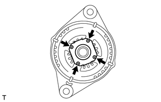
(a) Remove the 4 screws and bearing retainer from the drive end frame. |
|
|
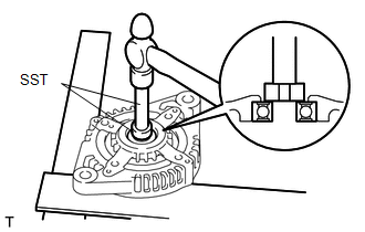
(b) Using SST and a hammer, tap out the drive end frame bearing from the drive end frame. SST: 09950-60010 09951-00250 SST: 09950-70010 09951-07100 |
|
|
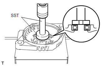
(c) Using SST and a press, press in a new generator drive end frame bearing. SST: 09950-60010 09951-00470 SST: 09950-70010 09951-07100 |
|
|
(d) Fit the tabs on the retainer plate into the cutouts on the drive end frame to install the retainer plate. Text in Illustration
|
|
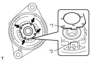
(e) Install the 4 screws.
Torque:
2.3 N·m {23 kgf·cm, 20 in·lbf}
 Inspection
INSPECTION
PROCEDURE
1. INSPECT GENERATOR CLUTCH PULLEY
(a) Hold the generator rotor using SST, and turn the clutch pulley clockwise
to check that the outer ring locks.
SST: 09820 ...
 Installation
INSTALLATION
PROCEDURE
1. INSTALL GENERATOR ASSEMBLY
(a) Install the wire harness clamp with the bolt.
Torque:
8.4 N·m {86 kgf·cm, 74 in·lbf}
...
Other materials about Toyota Venza:
Removal
REMOVAL
PROCEDURE
1. ALIGN FRONT WHEELS FACING STRAIGHT AHEAD
2. DISCONNECT CABLE FROM NEGATIVE BATTERY TERMINAL
CAUTION:
Wait at least 90 seconds after disconnecting the cable from the negative (-)
battery terminal to disable the SRS system.
NOTICE:
...
Ignition Coil "A" Primary / Secondary Circuit (P0351-P0354)
DESCRIPTION
HINT:
These DTCs indicate malfunctions relating to the primary circuit.
If DTC P0351 is output, check the No. 1 ignition coil circuit.
If DTC P0352 is output, check the No. 2 ignition coil circuit.
If DTC P0353 is output, c ...
Removal
REMOVAL
PROCEDURE
1. REMOVE INSTRUMENT PANEL SAFETY PAD ASSEMBLY
(See page )
2. REMOVE NO. 1 ANTENNA CORD SUB-ASSEMBLY
(a) Disengage the 7 clamps and remove the No. 1 antenna cord sub-assembly.
3. REMOVE ROOF HEADLINING ASSEMBLY
(See page )
4. REMO ...

0.1589