Toyota Venza: Removal
REMOVAL
PROCEDURE
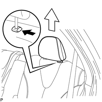
1. REMOVE REAR SEAT HEADREST ASSEMBLY
|
(a) Press the headrest support button and pull up the headrest as shown in the illustration to remove it. |
|
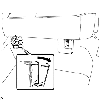
2. REMOVE REAR SEAT INNER TRACK BRACKET COVER
|
(a) Disengage the 3 claws and guide, and remove the rear seat inner track bracket cover as shown in the illustration. |
|
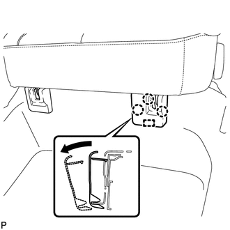
3. REMOVE REAR SEAT OUTER TRACK BRACKET COVER
|
(a) Disengage the 3 claws and guide, and remove the rear seat outer track bracket cover as shown in the illustration. |
|
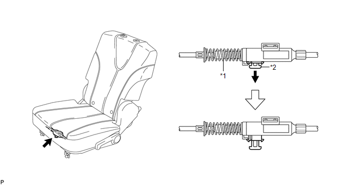
4. DISCONNECT REAR SEAT NO. 2 RECLINING CONTROL CABLE SUB-ASSEMBLY
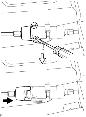
(a) Pull down the adjuster's lock piece to release the lock as shown in the illustration.
 Text in Illustration
|
*1 |
Adjuster Spring |
*2 |
Lock Piece |
|
(b) Using a screwdriver wrapped with protective tape, disengage the 2 claws as shown in the illustration. Text in Illustration
|
|
(c) Lift up the seat track adjusting handle to the uppermost position and hold the handle in this position as shown in the illustration.
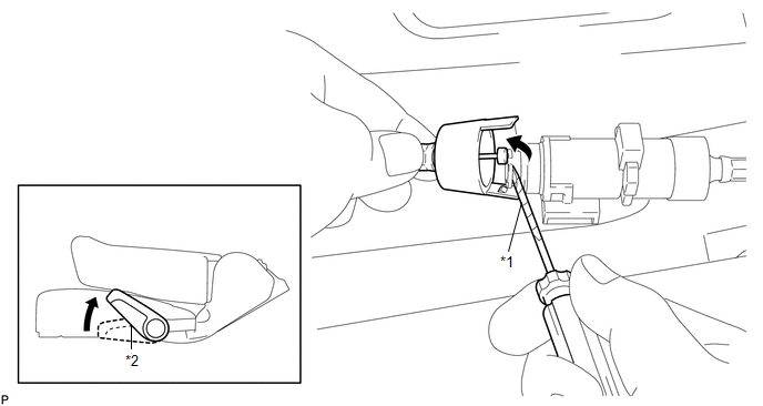 Text in Illustration
|
*1 |
Seat Track Adjusting Handle |
*2 |
Protective Tap |
(d) Using a screwdriver wrapped with protective tape, disconnect the rear seat reclining control cable sub-assembly as shown in the illustration.
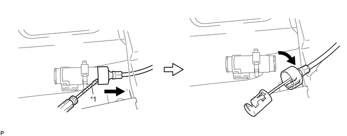 Text in Illustration
|
*1 |
Protective Tape |
(e) Secure the rear seat No. 2 reclining control cable sub-assembly with the carpet hole as shown in the illustration.
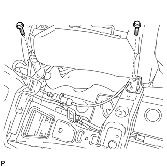
5. REMOVE REAR SEAT ASSEMBLY LH
|
(a) Remove the 2 bolts on the rear side of the seat. |
|
|
(b) Remove the 2 bolts on the front side of the seat. |
|
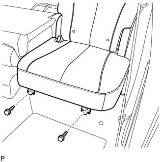
(c) Remove the rear seat assembly LH.
NOTICE:
Be careful not to damage the vehicle body.
 Components
COMPONENTS
ILLUSTRATION
ILLUSTRATION
ILLUSTRATION
ILLUSTRATION
...
 Disassembly
DISASSEMBLY
PROCEDURE
1. REMOVE SEAT ADJUSTER COVER CAP LH
(a) Using a screwdriver wrapped with protective tape, disengage the 3
claws and remove the seat adjuster cover cap LH.
T ...
Other materials about Toyota Venza:
Brake Pedal Load Sensing Switch
On-vehicle Inspection
ON-VEHICLE INSPECTION
PROCEDURE
1. INSPECT BRAKE PEDAL LOAD SENSING SWITCH
NOTICE:
Do not remove the brake pedal load sensing switch from the brake pedal
support assembly.
When there is a malfunction in the brake pe ...
Reassembly
REASSEMBLY
PROCEDURE
1. INSTALL SHIFT LOCK CONTROL COMPUTER SUB-ASSEMBLY
(a) Engage the 3 claws to install the shift lock control computer sub-assembly.
(b) Connect the connector.
2. INSTALL LOWER ...
Removal
REMOVAL
PROCEDURE
1. DISCONNECT CABLE FROM NEGATIVE BATTERY TERMINAL
CAUTION:
Wait at least 90 seconds after disconnecting the cable from the negative (-)
battery terminal to disable the SRS system.
NOTICE:
When disconnecting the cable, some systems ne ...

0.14