Toyota Venza: Power Back Door Touch Sensor
Components
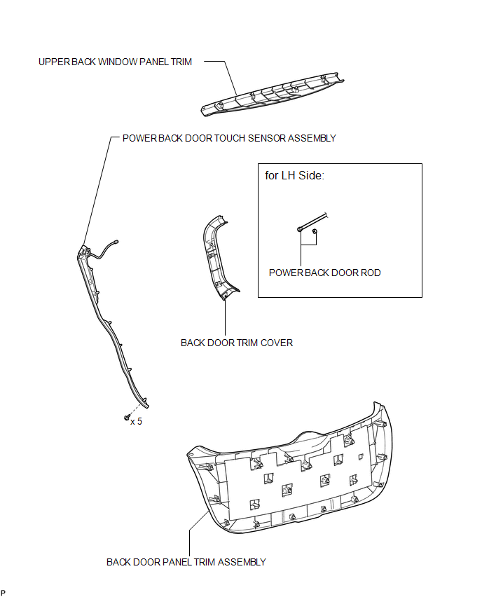
COMPONENTS
ILLUSTRATION
Removal
REMOVAL
PROCEDURE
1. REMOVE UPPER BACK WINDOW PANEL TRIM
.gif)
2. REMOVE BACK DOOR PANEL TRIM ASSEMBLY
3. DISCONNECT POWER BACK DOOR ROD (for LH Side)
4. REMOVE BACK DOOR TRIM COVER
5. REMOVE POWER BACK DOOR TOUCH SENSOR ASSEMBLY
|
(a) Disconnect the connector. |
|
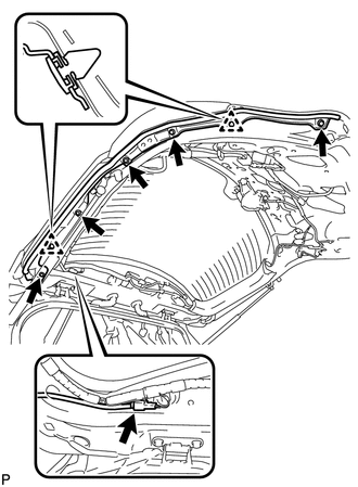
(b) Remove the 5 bolts.
(c) Disengage the 2 clips.
|
(d) Tie a string to the wire near the connector of the power back door touch sensor assembly. |
|
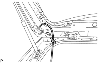
(e) Remove the power back door touch sensor assembly.
HINT:
Leave the string inside the back door frame because it will be used for installation.
(f) Untie the string from the power back door touch sensor assembly.
Inspection
INSPECTION
PROCEDURE
1. INSPECT POWER BACK DOOR TOUCH SENSOR LH
(a) Measure the resistance according to the value(s) in the table below.
.png)
Standard Resistance:
|
Tester Connection |
Condition |
Specified Condition |
|---|---|---|
|
1 (OSL) - 2 (OSLE) |
Not pressed |
950 to 1050 Ω |
|
1 (OSL) - 2 (OSLE) |
Pressed |
Below 100 Ω |
If the result is not as specified, replace the sensor.
2. INSPECT POWER BACK DOOR TOUCH SENSOR RH
(a) Measure the resistance according to the value(s) in the table below.
.png)
Standard Resistance:
|
Tester Connection |
Condition |
Specified Condition |
|---|---|---|
|
1 (OSR) - 2 (OSRE) |
Not pressed |
950 to 1050 Ω |
|
1 (OSR) - 2 (OSRE) |
Pressed |
Below 100 Ω |
If the result is not as specified, replace the sensor.
Installation
INSTALLATION
PROCEDURE
1. INSTALL POWER BACK DOOR TOUCH SENSOR ASSEMBLY
(a) Tie the string to the wire near the connector of the power back door touch sensor assembly.
HINT:
Use the string that was left in the door during removal of the touch sensor assembly.
|
(b) Pull the string to help pass the connector through the inside of the back door frame. |
|
.png)
|
(c) Engage the 2 clips. |
|
.png)
(d) Install the power back door touch sensor assembly with the 5 bolts.
(e) Connect the connector.
2. INSTALL BACK DOOR TRIM COVER
.gif)
3. CONNECT POWER BACK DOOR ROD (for LH Side)
4. INSTALL BACK DOOR PANEL TRIM ASSEMBLY
5. INSTALL UPPER BACK WINDOW PANEL TRIM
 Touch Sensor Circuit
DESCRIPTION
When the power back door ECU receives a jam signal from the touch sensor while
the power back door is operating, the ECU reverses the back door operation and opens
the door.
WIRING D ...
 Power Back Door Warning Buzzer
Components
COMPONENTS
ILLUSTRATION
Inspection
INSPECTION
PROCEDURE
1. INSPECT POWER BACK DOOR WARNING BUZZER
(a) Measure the resistance according to the value(s) in the table b ...
Other materials about Toyota Venza:
Outer Rear View Mirror Cover
Components
COMPONENTS
ILLUSTRATION
Installation
INSTALLATION
PROCEDURE
1. INSTALL OUTER MIRROR COVER
(a) Engage the 7 claws to install the outer mirror cover.
2. INSTALL OUTER MIRROR
R ...
Customize Parameters
CUSTOMIZE PARAMETERS
1. INTUITIVE PARKING ASSIST SYSTEM (See page
)
2. POWER DOOR LOCK CONTROL SYSTEM (See page
)
3. WIRELESS DOOR LOCK CONTROL SYSTEM (w/ Smart Key System) (See page
)
4. WIRELESS DOOR LOCK CONTROL SYSTEM (w/o Smart Key System) (Se ...
Back Door Motor Clutch Malfunction (B2225)
DESCRIPTION
When an electrical malfunction (open or short) is detected in the clutch circuit
of the power back door ECU (power back door motor unit) while the power back door
is operating, the power back door ECU (power back door motor unit) stores DTC B2 ...

0.16