Toyota Venza: Inspection
INSPECTION
PROCEDURE
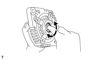
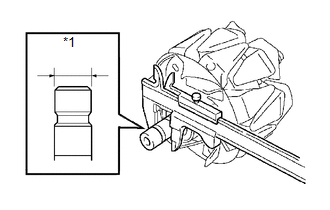
1. INSPECT GENERATOR CLUTCH PULLEY
|
(a) Hold the generator rotor using SST, and turn the clutch pulley clockwise to check that the outer ring locks. SST: 09820-63021 Text in Illustration
If the result is not as specified, replace the clutch pulley. |
|
.png)
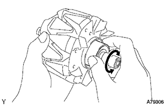
2. INSPECT GENERATOR DRIVE END FRAME BEARING
|
(a) Check that the bearing is not rough or worn. OK: The bearing rotates smoothly. If the bearing does not rotate smoothly, replace the bearing. |
|
3. INSPECT GENERATOR BRUSH HOLDER ASSEMBLY
|
(a) Using a vernier caliper, measure the length of the exposed brushes. Text in Illustration
Standard exposed brush length: 9.5 to 11.5 mm (0.375 to 0.452 in.) Minimum exposed brush length: 4.5 mm (0.178 in.) If the exposed brush length is less than the minimum, replace the brush holder assembly. |
|
.png)
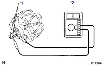
4. INSPECT GENERATOR ROTOR ASSEMBLY
|
(a) Check that the generator rotor bearing is not rough or worn. If necessary, replace the generator rotor assembly. |
|
|
(b) Check the generator rotor for an open circuit. Text in Illustration
(1) Using an ohmmeter, measure the resistance between the slip rings. Standard Resistance:
If the result is not as specified, replace the generator rotor assembly. |
|
||||||||||||||
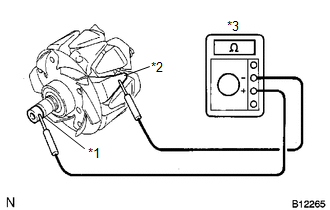
|
(c) Check the rotor for a short to ground. Text in Illustration
(1) Using an ohmmeter, measure the resistance between the slip ring and rotor. Standard Resistance:
If the result is not as specified, replace the generator rotor assembly. |
|
|
(d) Using a vernier caliper, measure the slip ring diameter. Text in Illustration
Standard diameter: 14.2 to 14.4 mm (0.560 to 0.566 in.) Minimum diameter: 14.0 mm (0.552 in.) If the diameter is less than the minimum, replace the generator rotor assembly. |
|
 Disassembly
DISASSEMBLY
PROCEDURE
1. REMOVE GENERATOR REAR END COVER
(a) Remove the 3 nuts and generator rear end cover.
2. REMOVE TERMINAL INSULATOR
...
 Replacement
REPLACEMENT
PROCEDURE
1. REPLACE GENERATOR DRIVE END FRAME BEARING
(a) Remove the 4 screws and bearing retainer from the drive end frame.
...
Other materials about Toyota Venza:
Lost Communication with Rear Airbag Sensor RH (B1632/81,B1633/81,B1642/81,B1692/81,B1693/81)
DESCRIPTION
The side collision sensor RH circuit (to determine deployment of the front seat
side airbag assembly RH and curtain shield airbag assembly RH) is composed of the
center airbag sensor assembly, rear airbag sensor RH and side airbag sensor RH.
...
Installation
INSTALLATION
PROCEDURE
1. INSTALL TIMING CHAIN COVER SUB-ASSEMBLY
(a) Apply a light coat of engine oil to 2 new oil pump gaskets and new
oil hole cover gasket.
(b) Install the 2 new oil pump gas ...
Removal
REMOVAL
PROCEDURE
1. REMOVE ENGINE ASSEMBLY WITH TRANSAXLE (for 2GR-FE)
HINT:
Refer to the procedure up to Remove Engine Assembly with Transaxle (See page
).
2. REMOVE ENGINE ASSEMBLY WITH TRANSAXLE (for 1AR-FE)
HINT:
Refer to the procedure up to Remo ...

0.1133