Toyota Venza: Removal
REMOVAL
PROCEDURE
1. DISCONNECT CABLE FROM NEGATIVE BATTERY TERMINAL
NOTICE:
When disconnecting the cable, some systems need to be initialized after the cable
is reconnected (See page .gif) ).
).
2. REMOVE COOL AIR INTAKE DUCT SEAL
3. REMOVE NO. 1 ENGINE COVER SUB-ASSEMBLY
4. REMOVE V-RIBBED BELT
HINT:
See page
5. REMOVE WIRE HARNESS CLAMP BRACKET
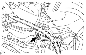
(a) Detach the wire harness clamp from the clamp bracket.
(b) Remove the bolt and clamp bracket.
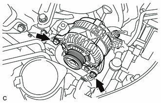
6. REMOVE GENERATOR ASSEMBLY
|
(a) Disconnect the generator connector. |
|
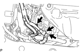
(b) Remove the terminal cap.
(c) Remove the nut and disconnect the generator wire.
(d) Remove the bolt and wire harness clamp bracket.
|
(e) Remove the 2 bolts and generator. |
|
 Components
COMPONENTS
ILLUSTRATION
ILLUSTRATION
ILLUSTRATION
...
 Disassembly
DISASSEMBLY
PROCEDURE
1. REMOVE GENERATOR PULLEY CAP
(a) Using a screwdriver, puncture the center of the generator pulley
cap and pry it off.
NOTICE:
Do not reuse the generator ...
Other materials about Toyota Venza:
Door Control Transmitter(w/ Smart Key System)
Components
COMPONENTS
ILLUSTRATION
Removal
REMOVAL
PROCEDURE
1. REMOVE TRANSMITTER BATTERY
Inspection
INSPECTION
PROCEDURE
1. INSPECT DOOR CONTROL TRANSMITTER
(a) Inspect operation of the transmitter.
(1) Remove the battery (lithium batt ...
System Description
SYSTEM DESCRIPTION
1. BRIEF DESCRIPTION
(a) The Control Area Network (CAN) is a serial data communication system for
real time application. It is a vehicle multiplex communication system which has
a high communication speed and the ability to detect malf ...
Front Passenger Side Solar Sensor Short Circuit (B14A3)
DESCRIPTION
The solar sensor is installed on the upper side of the instrument panel. It detects
sunlight to control air conditioning AUTO mode. The output voltage from the solar
sensor varies in accordance with the amount of sunlight. When the amount of ...

0.1667