Toyota Venza: Installation
INSTALLATION
PROCEDURE
1. INSTALL ECM
|
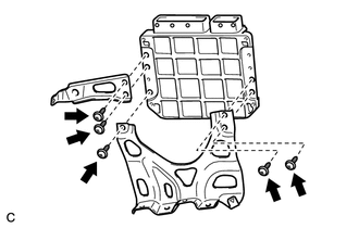
(a) Install the bracket to the ECM with the 5 screws. |
|
|
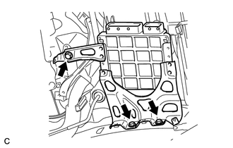
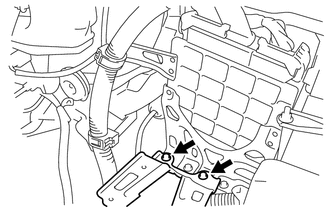
(b) Install the ECM with the 3 bolts. Torque: 8.0 N·m {82 kgf·cm, 71 in·lbf} |
|
|
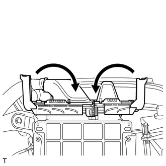
(c) Connect the 2 ECM connectors and lower the 2 levers. NOTICE:
|
|
|
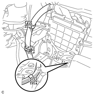
(d) Install the 3 wire harness clamps. |
|
2. INSTALL AIR CLEANER BRACKET
|
(a) Install the air cleaner bracket with the 2 bolts. Torque: 7.8 N·m {80 kgf·cm, 69 in·lbf} |
|
3. INSTALL AIR CLEANER CASE SUB-ASSEMBLY
.gif)
4. INSTALL AIR CLEANER FILTER ELEMENT SUB-ASSEMBLY
5. INSTALL AIR CLEANER CAP SUB-ASSEMBLY
6. INSTALL NO. 1 VACUUM SWITCHING VALVE ASSEMBLY
7. INSTALL NO. 1 ENGINE COVER SUB-ASSEMBLY
8. INSTALL OUTER COWL TOP PANEL SUB-ASSEMBLY
9. INSTALL WINDSHIELD WIPER MOTOR AND LINK
(a) Install the windshield wiper motor and link (See page
).
10. INSTALL COOL AIR INTAKE DUCT SEAL
11. CONNECT CABLE TO NEGATIVE BATTERY TERMINAL
CAUTION:
When disconnecting the cable, some systems need to be initialized after the cable
is reconnected (See page ).
12. PERFORM REGISTRATION
(a) The Vehicle Identification Number (VIN) must be input into a replacement
ECM (See page ).
 Components
COMPONENTS
ILLUSTRATION
ILLUSTRATION
...
 Removal
REMOVAL
PROCEDURE
1. REMOVE WINDSHIELD WIPER MOTOR AND LINK
(a) Remove the windshield wiper motor and link (See page
).
2. REMOVE OUTER COWL TOP PANEL SUB-ASSEMBLY
3. REMOVE COOL AIR INTAKE ...
Other materials about Toyota Venza:
Registering ID codes
The tire pressure warning valve and transmitter is equipped with a unique ID
code. When replacing a tire pressure warning valve and transmitter, it is necessary
to register the ID code of tire pressure warning valve and transmitter. Have the
ID code regi ...
Microphone Circuit between Microphone and Navigation Receiver Assembly
DESCRIPTION
The navigation receiver assembly and inner rear view mirror assembly
(amplifier microphone assembly) are connected to each other using the microphone
connection detection signal lines.
Using this circuit, the navigation receiver ...
Pressure Sensor Circuit (B1423/23)
DESCRIPTION
This DTC is output when refrigerant pressure on the high pressure side is extremely
low (190 kPa (1.9 kgf/cm2, 28 psi) or less) or extremely high (3140 kPa (32.0 kgf/cm2,
455 psi) or more). The A/C pressure sensor is installed on the high pres ...

0.1764