Toyota Venza: Removal
REMOVAL
PROCEDURE
1. DISCONNECT CABLE FROM NEGATIVE BATTERY TERMINAL
NOTICE:
When disconnecting the cable, some systems need to be initialized after the cable
is reconnected (See page .gif) ).
).
2. REMOVE NO. 1 ENGINE COVER SUB-ASSEMBLY
3. REMOVE COOL AIR INTAKE DUCT SEAL
4. REMOVE NO. 1 ENGINE UNDER COVER
5. REMOVE NO. 2 ENGINE UNDER COVER
6. DRAIN ENGINE COOLANT
7. REMOVE V-RIBBED BELT
HINT:
See page
8. REMOVE WIRE HARNESS CLAMP BRACKET
9. REMOVE GENERATOR ASSEMBLY
10. REMOVE V-RIBBED BELT TENSIONER ASSEMBLY
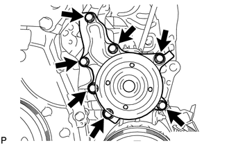
11. REMOVE WATER PUMP ASSEMBLY
|
(a) Remove the 7 bolts, water pump and water pump gasket. |
|
 On-vehicle Inspection
ON-VEHICLE INSPECTION
PROCEDURE
1. INSPECT FOR COOLANT LEAK
HINT:
The sliding surface inside the engine water pump assembly is lubricated
by engine coolant. As some engine coolant is d ...
 Installation
INSTALLATION
PROCEDURE
1. INSTALL WATER PUMP ASSEMBLY
(a) Install a new gasket and the water pump with the 7 bolts.
Torque:
21 N·m {214 kgf·cm, 15 ft·lbf}
...
Other materials about Toyota Venza:
Components
COMPONENTS
ILLUSTRATION
ILLUSTRATION
ILLUSTRATION
ILLUSTRATION
ILLUSTRATION
...
Regulations on the use of tire chains
• Regulations regarding the use of tire chains vary according to location and
type of road. Always check local regulations before installing chains.
• Retighten the chains after driving 1/4 - 1/2 mile (0.5 - 1.0 km).
- Tire chains
Observe the fo ...
Air Conditioning Amplifier
Components
COMPONENTS
ILLUSTRATION
Installation
INSTALLATION
PROCEDURE
1. INSTALL AIR CONDITIONING AMPLIFIER ASSEMBLY
(a) Install the air conditioning amplifier assembly with the 2 screws.
...

0.1163