Toyota Venza: Seat Position Sensor
Components
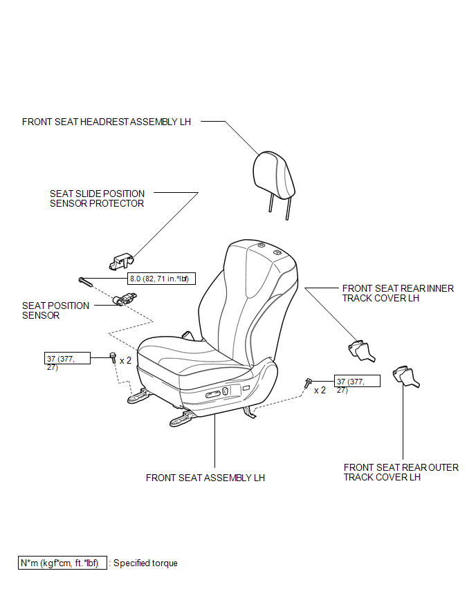
COMPONENTS
ILLUSTRATION
On-vehicle Inspection
ON-VEHICLE INSPECTION
CAUTION / NOTICE / HINT
CAUTION:
Be sure to follow the correct removal and installation procedures of the seat position sensor.
PROCEDURE
1. INSPECT SEAT POSITION SENSOR (VEHICLE NOT INVOLVED IN COLLISION)
(a) Perform a diagnostic system check (See page
.gif) ).
).
2. INSPECT SEAT POSITION SENSOR (VEHICLE INVOLVED IN COLLISION AND AIRBAG HAS NOT DEPLOYED)
(a) Perform a diagnostic system check (See page
).
(b) Visually check for defects with the seat position sensor installed on the vehicle.
(1) The defects are as follows:
- Cracks on the sensor housing
- Dents on the sensor housing
- Chips on the sensor housing
- Cracks or other damage to the connector
OK:
No defects are found.
HINT:
If any of the defects is found, replace the seat position sensor with a new one.
Removal
REMOVAL
PROCEDURE
1. PRECAUTION
CAUTION:
Be sure to read Precaution thoroughly before servicing (See page
.gif) ).
).
2. REMOVE FRONT SEAT ASSEMBLY LH
(See page )
3. REMOVE SEAT POSITION SENSOR
|
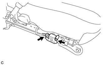
(a) Disconnect the connector. |
|
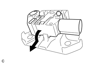
(b) Using a T30 "TORX" socket wrench, remove the "TORX" screw and seat position sensor with the seat slide position sensor protector.
|
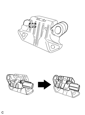
(c) Remove the seat position sensor from the seat slide position sensor protector as shown in the illustration. |
|
Installation
INSTALLATION
PROCEDURE
1. INSTALL SEAT POSITION SENSOR
|
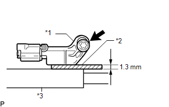
(a) Install the seat position sensor to the seat slide position sensor protector with the pin as shown in the illustration. |
|
|
(b) Using a 1.3 mm (0.0512 in.) feeler gauge, temporarily install the seat position sensor. Text in Illustration
NOTICE:
HINT: Be sure that the clearance between the seat position sensor and the seat rail is within 0.6 mm (0.0236 in.) to 2.0 mm (0.0787 in.). |
|
|
(c) Using a T30 "TORX" socket wrench, tighten the "TORX" screw to install the seat position sensor. Torque: 8.0 N·m {82 kgf·cm, 71 in·lbf} |
|
.png)
(d) Make sure that the clearance between the seat position sensor and the seat rail is within 0.6 mm (0.0236 in.) to 2.0 mm (0.0787 in.).
(e) Connect the connector.
(f) Check that there is no looseness in the installation parts of the seat position sensor.
2. INSTALL FRONT SEAT ASSEMBLY LH
(See page .gif) )
)
3. PERFORM DIAGNOSTIC SYSTEM CHECK
(a) Perform a diagnostic system check (See page
).
4. INSPECT SRS WARNING LIGHT
(a) Inspect the SRS warning light (See page
).
 Removal
REMOVAL
CAUTION / NOTICE / HINT
HINT:
Use the same procedure for the RH side and LH side.
The procedure listed below is for the LH side.
PROCEDURE
1. PRECAUTION
CAUTION:
Be su ...

Other materials about Toyota Venza:
Data List / Active Test
DATA LIST / ACTIVE TEST
1. DATA LIST
HINT:
Using the Techstream to read the Data List allows the values or states of switches,
sensors, actuators and other items to be read without removing any parts. This non-intrusive
inspection can be very useful bec ...
On-vehicle Inspection
ON-VEHICLE INSPECTION
PROCEDURE
1. INSPECT CENTER AIRBAG SENSOR ASSEMBLY (VEHICLE NOT INVOLVED IN COLLISION)
(a) Perform a diagnostic system check (See page
).
2. INSPECT CENTER AIRBAG SENSOR ASSEMBLY (VEHICLE INVOLVED IN COLLISION AND AIRBAG
HAS NOT D ...
Removal
REMOVAL
PROCEDURE
1. PRECAUTION
CAUTION:
Be sure to read Precaution thoroughly before servicing (See page
).
If the front seat side airbag assembly was deployed, replace the front
seat side airbag assembly, front seat frame assembly wit ...

0.1138