
Toyota Venza: Components
COMPONENTS
ILLUSTRATION
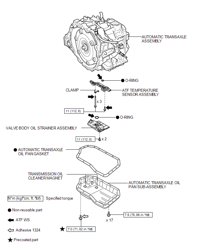

 Removal
REMOVAL
PROCEDURE
1. REMOVE AUTOMATIC TRANSAXLE ASSEMBLY
HINT:
See the steps from "Remove Engine Assembly with transaxle" through "Remove Automatic
Transaxle Assembly" (See p ...
Other materials about Toyota Venza:
Inspection
INSPECTION
PROCEDURE
1. INSPECT WINDSHIELD WIPER SWITCH ASSEMBLY
(a) Measure the resistance according to the value(s) in the table below.
Standard Resistance:
Front Wiper Switch
Tester Connection
Switch ...
Cruise SET Indicator Light Circuit
DESCRIPTION
The ECM detects a cruise control switch signal and sends it to the combination
meter assembly through CAN. Then the SET indicator light comes on.
The SET indicator light circuit uses CAN for communication. If there
is a malfunct ...
Removal
REMOVAL
PROCEDURE
1. REMOVE ENGINE ASSEMBLY WITH TRANSAXLE
See page for 2GR-FE
See page for 1AR-FE
2. REMOVE FRONT NO. 1 STABILIZER BRACKET LH
3. REMOVE FRONT NO. 1 STABILIZER BRACKET RH
HINT:
Perform the same procedure as for the LH side.
4. REM ...

0.1759