Toyota Venza: Electrical Key Oscillator(for Center Floor)
Components
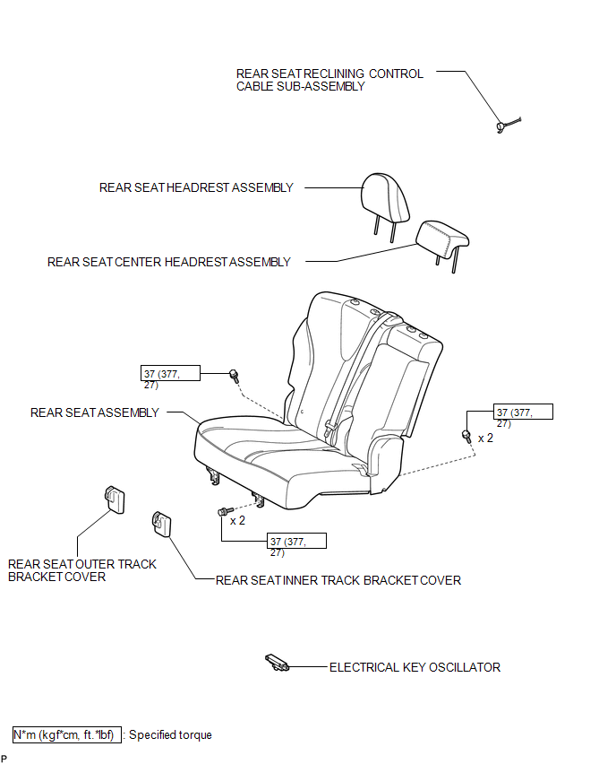
COMPONENTS
ILLUSTRATION
Installation
INSTALLATION
PROCEDURE
1. INSTALL ELECTRICAL KEY OSCILLATOR
|
(a) Engage the clamp and install the electrical key oscillator. NOTICE: Be careful when installing the electrical key oscillator. If the oscillator is dropped, replace it with a new one. |
|
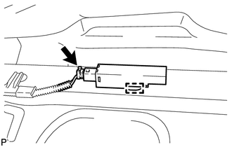
(b) Connect the connector.
2. INSTALL REAR SEAT ASSEMBLY
.gif)
3. CONNECT REAR SEAT RECLINING CONTROL CABLE SUB-ASSEMBLY
4. INSTALL REAR SEAT OUTER TRACK BRACKET COVER
5. INSTALL REAR SEAT INNER TRACK BRACKET COVER
6. INSTALL REAR SEAT CENTER HEADREST ASSEMBLY
7. INSTALL REAR SEAT HEADREST ASSEMBLY
Removal
REMOVAL
PROCEDURE
1. REMOVE REAR SEAT HEADREST ASSEMBLY
.gif)
2. REMOVE REAR SEAT CENTER HEADREST ASSEMBLY
3. REMOVE REAR SEAT INNER TRACK BRACKET COVER
4. REMOVE REAR SEAT OUTER TRACK BRACKET COVER
5. DISCONNECT REAR SEAT RECLINING CONTROL CABLE SUB-ASSEMBLY
6. REMOVE REAR SEAT ASSEMBLY
7. REMOVE ELECTRICAL KEY OSCILLATOR
|
(a) Disconnect the connector. |
|
.png)
(b) Disengage the clamp and the electrical key oscillator.
NOTICE:
Be careful when removing the electrical key oscillator. If the oscillator is dropped, replace it with a new one.
 Certification Ecu
Components
COMPONENTS
ILLUSTRATION
Removal
REMOVAL
PROCEDURE
1. DISCONNECT CABLE FROM NEGATIVE BATTERY TERMINAL
CAUTION:
Wait at least 90 seconds after disconnecting the cable from the n ...
 Electrical Key Oscillator(for Front Floor)
Components
COMPONENTS
ILLUSTRATION
Installation
INSTALLATION
PROCEDURE
1. INSTALL ELECTRICAL KEY OSCILLATOR
(a) Engage the clamp and install the electrical key oscillator.
N ...
Other materials about Toyota Venza:
Passenger Airbag ON/OFF Indicator Circuit Malfunction (B1660/43)
DESCRIPTION
The passenger airbag ON/OFF indicator circuit consists of the center airbag sensor
assembly and accessory meter assembly (passenger airbag ON/OFF indicator).
The passenger airbag ON/OFF indicator indicates the operation condition of the
front ...
Installation
INSTALLATION
CAUTION / NOTICE / HINT
NOTICE:
When disconnecting the steering intermediate shaft assembly and pinion shaft
of the steering gear assembly, be sure to place matchmarks before servicing.
PROCEDURE
1. INSTALL TIE ROD ASSEMBLY LH
( ...
Air Conditioning Control Panel Circuit
DESCRIPTION
This circuit consists of the air conditioning control assembly and the A/C amplifier.
When the air conditioning control assembly is operated, signals are transmitted
to the A/C amplifier through the LIN communication system.
If the LIN commun ...

0.1603