Toyota Venza: Removal
REMOVAL
PROCEDURE
1. REMOVE TAIL EXHAUST PIPE ASSEMBLY (for 1AR-FE)
.gif)
2. REMOVE TAIL EXHAUST PIPE ASSEMBLY (for 2GR-FE)
3. REMOVE CENTER EXHAUST PIPE ASSEMBLY (for 1AR-FE)
4. REMOVE CENTER EXHAUST PIPE ASSEMBLY (for 2GR-FE)
5. REMOVE PROPELLER WITH CENTER BEARING SHAFT ASSEMBLY
(a) Depress the brake pedal and hold it.
|
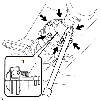
(b) Using a hexagon wrench (6 mm), loosen the cross groove joint set bolts 1/2 turn. NOTICE:
|
|
|
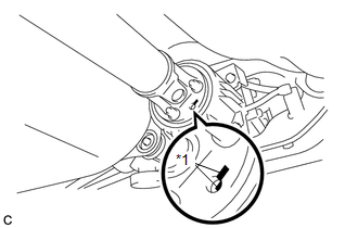
(c) Place matchmarks on the rear propeller shaft and electromagnetic control coupling assembly. Text in Illustration
|
|
|
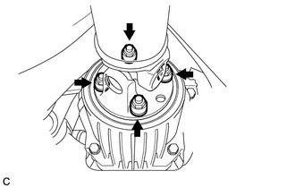
(d) Remove the 4 nuts and 4 washers. |
|
|
(e) Using a brass bar and a hammer, separate the propeller with center bearing shaft assembly. |
|
|
(f) Remove the 4 bolts, 2 No. 1 center support bearing washers and 2 No. 2 center support bearing washers. NOTICE: When removing the bolts and washers, do not apply excessive force to the universal joint. |
|
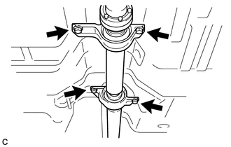
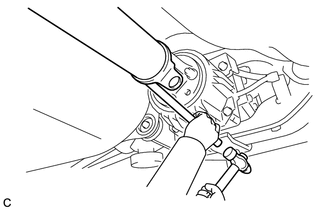
(g) Pull out the propeller with center bearing shaft assembly from the transfer.
NOTICE:
- When removing the propeller shaft, do not apply excessive force to the universal joint.
- During and after the removal of the propeller shaft, keep the universal joint angle straight (within 15 degrees).
- Be careful not to damage the oil seal.
|
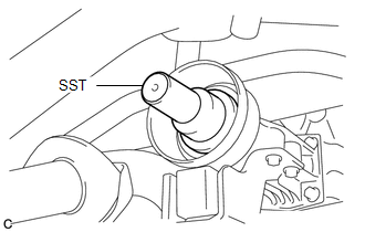
(h) Insert SST into the transfer to prevent oil leaks. SST: 09325-20010 NOTICE: Be careful not to damage the oil seal. |
|
 Components
COMPONENTS
ILLUSTRATION
ILLUSTRATION
ILLUSTRATION
ILLUSTRATION
...
 Disassembly
DISASSEMBLY
PROCEDURE
1. REMOVE PROPELLER SHAFT
(a) Place matchmarks on both flanges.
Text in Illustration
*1
Matchmark
...
Other materials about Toyota Venza:
Inspection
INSPECTION
PROCEDURE
1. INSPECT CYLINDER BLOCK FOR WARPAGE
(a) Using a precision straightedge and feeler gauge, check the surface
that is in contact with the cylinder head gasket for warpage.
Maximum Warpage:
0.05 mm (0.00197 in.)
I ...
Main Body ECU Vehicle Information Reading/Writing Process Malfunction (B15F6)
DESCRIPTION
This DTC is stored when items controlled by the main body ECU (multiplex network
body ECU) cannot be customized via the audio and visual system vehicle customization
screen.
HINT:
The main body ECU (multiplex network body ECU) controls t ...
Installation
INSTALLATION
PROCEDURE
1. INSTALL AIR CONDITIONING UNIT ASSEMBLY
(a) Install the air conditioning unit assembly with the 3 nuts.
Torque:
9.8 N·m {100 kgf·cm, 87 in·lbf}
NOTICE:
Tighten the nuts in the order shown in the illustration to install the ...

0.1319