Toyota Venza: On-vehicle Inspection
ON-VEHICLE INSPECTION
PROCEDURE
1. INSPECT BRAKE BOOSTER ASSEMBLY
|
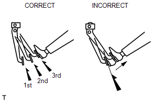
(a) Airtightness check (1) Start the engine and stop it after 1 or 2 minutes. Slowly depress the brake pedal several times. HINT: If the pedal can be depressed to the floor the first time, but on the 2nd and 3rd time cannot be depressed as far, the booster is airtight. (2) Depress the brake pedal while the engine is running, and stop the engine with the pedal depressed. HINT: If there is no change in the pedal reserve distance while holding the pedal depressed for 30 seconds, the booster is airtight. |
|
(b) Operation check
|
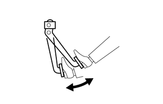
(1) Depress the brake pedal several times with the ignition switch off and check that there is no change in the pedal reserve distance when the pedal is depressed. |
|
|
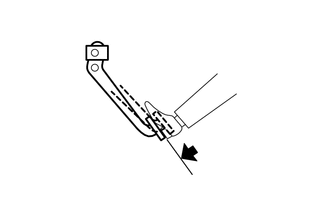
(2) Depress and hold the brake pedal, then start the engine. HINT: If the pedal goes down slightly, operation is normal. |
|
 Components
COMPONENTS
ILLUSTRATION
ILLUSTRATION
ILLUSTRATION
ILLUSTRATION
ILLUSTRATION
...
 Removal
REMOVAL
CAUTION / NOTICE / HINT
NOTICE:
Release the vacuum from the booster by depressing the brake pedal several times.
Then remove the brake master cylinder from the brake booster.
PROCEDURE
...
Other materials about Toyota Venza:
Terminals Of Ecu
TERMINALS OF ECU
1. CHECK MAIN BODY ECU (DRIVER SIDE JUNCTION BLOCK ASSEMBLY)
(a) Disconnect the main body ECU (driver side junction block assembly) connectors.
(b) Measure the resistance and voltage according to the value(s) in the table
below.
...
Blower Motor Circuit
DESCRIPTION
The blower motor is operated by signals from the A/C amplifier. Blower motor
speed signals are transmitted in accordance with changes in the duty ratio.
WIRING DIAGRAM
CAUTION / NOTICE / HINT
NOTICE:
Inspect the fuses for circuits related ...
Removal
REMOVAL
PROCEDURE
1. REMOVE FRONT SEAT HEADREST ASSEMBLY
2. REMOVE FRONT SEAT REAR OUTER TRACK COVER
3. REMOVE FRONT SEAT REAR INNER TRACK COVER
4. REMOVE FRONT SEAT ASSEMBLY
5. REMOVE RECLINING POWER SEAT SWITCH KNOB
6. REMOVE SLIDE AND VER ...

0.1544