Toyota Venza: Power Window Switch Malfunction (B2312)
DESCRIPTION
The power window regulator motor assembly is operated by the power window regulator master switch assembly or power window regulator switch assembly. The power window regulator motor assembly has motor, regulator and ECU functions.
This DTC is output when the ECU built into the regulator motor determines that the power window regulator master switch assembly or power window regulator switch assembly is stuck.
HINT:
DTC B2312 can be stored in the power window regulator master switch assembly and in each power window regulator motor assembly (power window ECU).
Master Switch (Power Window Regulator Master Switch Assembly)|
DTC No. |
DTC Detection Condition |
Trouble Area |
|---|---|---|
|
B2312 |
|
Power window regulator master switch assembly |
|
DTC No. |
DTC Detection Condition |
Trouble Area |
|---|---|---|
|
B2312 |
|
|
|
DTC No. |
DTC Detection Condition |
Trouble Area |
|---|---|---|
|
B2312 |
|
|
|
DTC No. |
DTC Detection Condition |
Trouble Area |
|---|---|---|
|
B2312 |
|
|
|
DTC No. |
DTC Detection Condition |
Trouble Area |
|---|---|---|
|
B2312 |
|
|
WIRING DIAGRAM
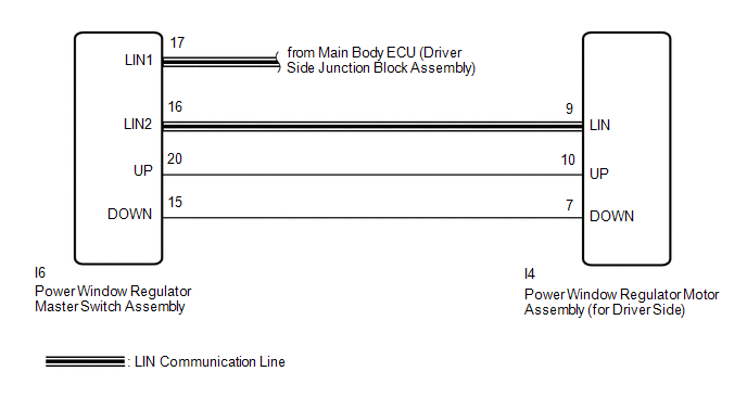
1. for Driver Side
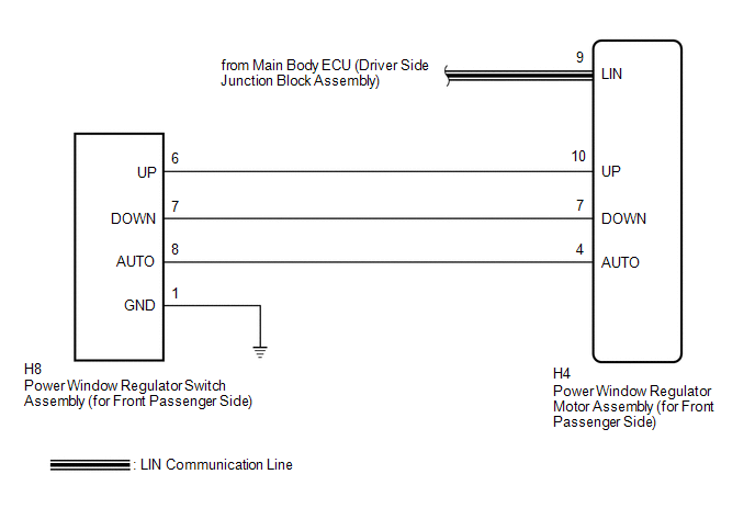
2. for Front Passenger Side
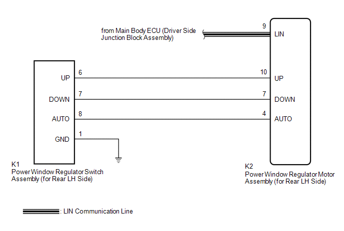
3. for Rear LH Side
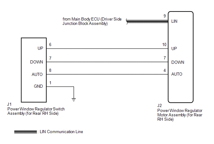
4. for Rear RH Side
CAUTION / NOTICE / HINT
NOTICE:
- When the power window regulator motor assembly is reinstalled or replaced, the power window control system must be initialized.
- After a door glass or a door glass run has been replaced, the jam protection
function may operate unexpectedly when the auto up function is used. In
such cases, the auto up function can be reinitialized by repeating the following
operations at least 5 times:
- Close the power window by fully pulling up the power window regulator master switch assembly or power window regulator switch assembly and holding it at the auto up position.
- Open the power window by fully pushing down the switch.
PROCEDURE
|
1. |
CHECK DTC OUTPUT |
(a) Clear the DTC (See page .gif) ).
).
(b) Check for DTCs (See page ).
OK:
No DTCs output.
| OK | .gif) |
END (DUE TO SWITCH BEING OPERATED FOR 20 SECONDS OR MORE) |
|
.gif)
|
2. |
CHECK DTC |
(a) Check for DTC output conditions.
|
Result |
Proceed to |
|---|---|
|
DTC output from power window regulator master switch assembly |
A |
|
DTC output from power window regulator motor assembly (for driver side) |
B |
|
DTC output from power window regulator motor assembly (for front passenger side) |
C |
|
DTC output from power window regulator motor assembly (for rear LH side) |
D |
|
DTC output from power window regulator motor assembly (for rear RH side) |
E |
| A | |
REPLACE POWER WINDOW REGULATOR MASTER SWITCH ASSEMBLY |
| C | |
GO TO STEP 5 |
| D | |
GO TO STEP 8 |
| E | |
GO TO STEP 11 |
|
|
3. |
READ VALUE USING TECHSTREAM (D-Door Motor) |
(a) Connect the Techstream to the DLC3.
(b) Turn the ignition switch to ON.
(c) Turn the Techstream on.
(d) Enter the following menus: Body / D-Door Motor / Data List.
(e) Read the Data List according to the display on the Techstream.
D-Door Motor (Power Window Regulator Motor Assembly (for Driver Side))|
Tester Display |
Measurement Item/Range |
Normal Condition |
Diagnostic Note |
|---|---|---|---|
|
D Door P/W Up SW |
Driver side power window manual up switch signal / ON or OFF |
ON: Driver door power window manual up switch operated OFF: Driver door power window manual up switch not operated |
- |
|
D Door P/W Down SW |
Driver side power window manual down switch signal / ON or OFF |
ON: Driver door power window manual down switch operated OFF: Driver door power window manual down switch not operated |
- |
OK:
On the Techstream screen, ON or OFF is displayed accordingly.
| OK | |
REPLACE POWER WINDOW REGULATOR MOTOR ASSEMBLY (for Driver Side) |
|
|
4. |
CHECK HARNESS AND CONNECTOR (MASTER SWITCH - DRIVER SIDE MOTOR) |
(a) Disconnect the power window regulator master switch assembly connector.
|
(b) Disconnect the power window regulator motor assembly (for driver side) connector. |
|
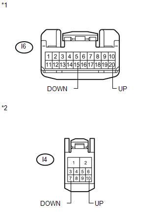
(c) Measure the resistance according to the value(s) in the table below.
Standard Resistance:
|
Tester Connection |
Condition |
Specified Condition |
|---|---|---|
|
I6-20 (UP) - Body ground |
Always |
10 kΩ or higher |
|
I6-15 (DOWN) - Body ground |
Always |
10 kΩ or higher |
|
I4-10 (UP) - Body ground |
Always |
10 kΩ or higher |
|
I4-7 (DOWN) - Body ground |
Always |
10 kΩ or higher |
|
*1 |
Front view of wire harness connector (to Power Window Regulator Master Switch Assembly) |
|
*2 |
Front view of wire harness connector (to Power Window Regulator Motor Assembly (for Driver Side)) |
| OK | |
REPLACE POWER WINDOW REGULATOR MOTOR ASSEMBLY (for Driver Side) |
| NG | |
REPAIR OR REPLACE HARNESS OR CONNECTOR |
|
5. |
READ VALUE USING TECHSTREAM (P-Door Motor) |
(a) Connect the Techstream to the DLC3.
(b) Turn the ignition switch to ON.
(c) Turn the Techstream on.
(d) Enter the following menus: Body / P-Door Motor / Data List.
(e) Read the Data List according to the display on the Techstream.
P-Door Motor (Power Window Regulator Motor Assembly (for Front Passenger Side))|
Tester Display |
Measurement Item/Range |
Normal Condition |
Diagnostic Note |
|---|---|---|---|
|
P Door P/W Auto SW |
Front passenger side power window auto up/down switch signal / ON or OFF |
ON: Front passenger side door power window auto switch operated OFF: Front passenger side door power window auto switch not operated |
- |
|
P Door P/W Up SW |
Front passenger side power window manual up switch signal / ON or OFF |
ON: Front passenger side door power window manual up switch operated OFF: Front passenger side door power window manual up switch not operated |
- |
|
P Door P/W Down SW |
Front passenger side power window manual down switch signal / ON or OFF |
ON: Front passenger side door power window manual down switch operated OFF: Front passenger side door power window manual down switch not operated |
- |
OK:
On the Techstream screen, ON or OFF is displayed accordingly.
| OK | |
REPLACE POWER WINDOW REGULATOR MOTOR ASSEMBLY (for Front Passenger Side) |
|
|
6. |
INSPECT POWER WINDOW REGULATOR SWITCH ASSEMBLY (for Front Passenger Side) |
|
(a) Remove the power window regulator switch assembly (for front passenger
side) (See page |
|
.png)
(b) Measure the resistance according to the value(s) in the table below.
Standard Resistance:
|
Tester Connection |
Condition |
Specified Condition |
|---|---|---|
|
6 (UP) - 1 (GND) |
Auto up or up position |
Below 1 Ω |
|
7 (DOWN) - 1 (GND) |
Auto down or down position |
Below 1 Ω |
|
8 (AUTO) - 1 (GND) |
Auto up or auto down position |
Below 1 Ω |
|
6 (UP) - 1 (GND) |
Free |
10 kΩ or higher |
|
7 (DOWN) - 1 (GND) |
Free |
10 kΩ or higher |
|
8 (AUTO) - 1 (GND) |
Free |
10 kΩ or higher |
|
*1 |
Component without harness connected (Power Window Regulator Switch Assembly (for Front Passenger Side)) |
| NG | |
REPLACE POWER WINDOW REGULATOR SWITCH ASSEMBLY (for Front Passenger Side) |
|
|
7. |
CHECK HARNESS AND CONNECTOR (FRONT PASSENGER SIDE SWITCH - FRONT PASSENGER SIDE MOTOR) |
|
(a) Disconnect the power window regulator motor assembly (for front passenger side) connector. |
|

(b) Measure the resistance according to the value(s) in the table below.
Standard Resistance:
|
Tester Connection |
Condition |
Specified Condition |
|---|---|---|
|
H8-6 (UP) - Body ground |
Always |
10 kΩ or higher |
|
H8-7 (DOWN) - Body ground |
Always |
10 kΩ or higher |
|
H8-8 (AUTO) - Body ground |
Always |
10 kΩ or higher |
|
H4-10 (UP) - Body ground |
Always |
10 kΩ or higher |
|
H4-7 (DOWN) - Body ground |
Always |
10 kΩ or higher |
|
H4-4 (AUTO) - Body ground |
Always |
10 kΩ or higher |
|
*1 |
Front view of wire harness connector (to Power Window Regulator Switch Assembly (for Front Passenger Side)) |
|
*2 |
Front view of wire harness connector (to Power Window Regulator Motor Assembly (for Front Passenger Side)) |
| OK | |
REPLACE POWER WINDOW REGULATOR MOTOR ASSEMBLY (for Front Passenger Side) |
| NG | |
REPAIR OR REPLACE HARNESS OR CONNECTOR |
|
8. |
READ VALUE USING TECHSTREAM (RL-Door Motor) |
(a) Connect the Techstream to the DLC3.
(b) Turn the ignition switch to ON.
(c) Turn the Techstream on.
(d) Enter the following menus: Body / RL-Door Motor / Data List.
(e) Read the Data List according to the display on the Techstream.
RL-Door Motor (Power Window Regulator Motor Assembly (for Rear LH Side))|
Tester Display |
Measurement Item/Range |
Normal Condition |
Diagnostic Note |
|---|---|---|---|
|
RL Door P/W Auto SW |
Rear LH side power window auto up/down switch signal / ON or OFF |
ON: Rear LH door power window auto switch operated OFF: Rear LH door power window auto switch not operated |
- |
|
RL Door P/W Up SW |
Rear LH side power window manual up switch signal / ON or OFF |
ON: Rear LH door power window manual up switch operated OFF: Rear LH door power window manual up switch not operated |
- |
|
RL Door P/W Down SW |
Rear LH side power window manual down switch signal / ON or OFF |
ON: Rear LH door power window manual down switch operated OFF: Rear LH door power window manual down switch not operated |
- |
OK:
On the Techstream screen, ON or OFF is displayed accordingly.
| OK | |
REPLACE POWER WINDOW REGULATOR MOTOR ASSEMBLY (for Rear LH side) |
|
|
9. |
INSPECT POWER WINDOW REGULATOR SWITCH ASSEMBLY (for Rear LH Side) |
|
(a) Remove the power window regulator switch assembly (for rear LH side)
(See page |
|
(b) Measure the resistance according to the value(s) in the table below.
Standard Resistance:
|
Tester Connection |
Condition |
Specified Condition |
|---|---|---|
|
6 (UP) - 1 (GND) |
Auto up or up position |
Below 1 Ω |
|
7 (DOWN) - 1 (GND) |
Auto down or down position |
Below 1 Ω |
|
8 (AUTO) - 1 (GND) |
Auto up or auto down position |
Below 1 Ω |
|
6 (UP) - 1 (GND) |
Free |
10 kΩ or higher |
|
7 (DOWN) - 1 (GND) |
Free |
10 kΩ or higher |
|
8 (AUTO) - 1 (GND) |
Free |
10 kΩ or higher |
|
*1 |
Component without harness connected (Power Window Regulator Switch Assembly (for Rear LH Side)) |
| NG | |
REPLACE POWER WINDOW REGULATOR SWITCH ASSEMBLY (for Rear LH side) |
|
|
10. |
CHECK HARNESS AND CONNECTOR (REAR LH SWITCH - REAR LH MOTOR) |
|
(a) Disconnect the power window regulator motor assembly (for rear LH side) connector. |
|
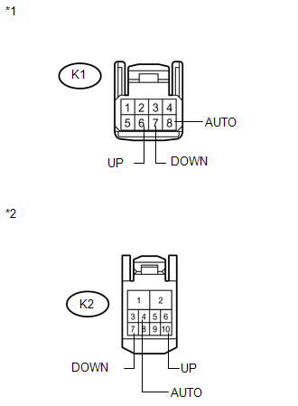
(b) Measure the resistance according to the value(s) in the table below.
Standard Resistance:
|
Tester Connection |
Condition |
Specified Condition |
|---|---|---|
|
K1-6 (UP) - Body ground |
Always |
10 kΩ or higher |
|
K1-7 (DOWN) - Body ground |
Always |
10 kΩ or higher |
|
K1-8 (AUTO) - Body ground |
Always |
10 kΩ or higher |
|
K2-10 (UP) - Body ground |
Always |
10 kΩ or higher |
|
K2-7 (DOWN) - Body ground |
Always |
10 kΩ or higher |
|
K2-4 (AUTO) - Body ground |
Always |
10 kΩ or higher |
|
*1 |
Front view of wire harness connector (to Power Window Regulator Switch Assembly (for Rear LH Side)) |
|
*2 |
Front view of wire harness connector (to Power Window Regulator Motor Assembly (for Rear LH Side)) |
| OK | |
REPLACE POWER WINDOW REGULATOR MOTOR ASSEMBLY (for Rear LH side) |
| NG | |
REPAIR OR REPLACE HARNESS OR CONNECTOR |
|
11. |
READ VALUE USING TECHSTREAM (RR-Door Motor) |
(a) Connect the Techstream to the DLC3.
(b) Turn the ignition switch to ON.
(c) Turn the Techstream on.
(d) Enter the following menus: Body / RR-Door Motor / Data List.
(e) Read the Data List according to the display on the Techstream.
RR-Door Motor (Power Window Regulator Motor Assembly (for Rear RH Side))|
Tester Display |
Measurement Item/Range |
Normal Condition |
Diagnostic Note |
|---|---|---|---|
|
RR Door P/W Auto SW |
Rear RH side power window auto up/down switch signal / ON or OFF |
ON: Rear RH door power window auto switch operated OFF: Rear RH door power window auto switch not operated |
- |
|
RR Door P/W Up SW |
Rear RH side power window manual up switch signal / ON or OFF |
ON: Rear RH door power window manual up switch operated OFF: Rear RH door power window manual up switch not operated |
- |
|
RR Door P/W Down SW |
Rear RH side power window manual down switch signal / ON or OFF |
ON: Rear RH door power window manual down switch operated OFF: Rear RH door power window manual down switch not operated |
- |
OK:
On the Techstream screen, ON or OFF is displayed accordingly.
| OK | |
REPLACE POWER WINDOW REGULATOR MOTOR ASSEMBLY (for Rear RH side) |
|
|
12. |
INSPECT POWER WINDOW REGULATOR SWITCH ASSEMBLY (for Rear RH Side) |
|
(a) Remove the power window regulator switch assembly (for rear RH side)
(See page |
|
(b) Measure the resistance according to the value(s) in the table below.
Standard Resistance:
|
Tester Connection |
Condition |
Specified Condition |
|---|---|---|
|
6 (UP) - 1 (GND) |
Auto up or up position |
Below 1 Ω |
|
7 (DOWN) - 1 (GND) |
Auto down or down position |
Below 1 Ω |
|
8 (AUTO) - 1 (GND) |
Auto up or auto down position |
Below 1 Ω |
|
6 (UP) - 1 (GND) |
Free |
10 kΩ or higher |
|
7 (DOWN) - 1 (GND) |
Free |
10 kΩ or higher |
|
8 (AUTO) - 1 (GND) |
Free |
10 kΩ or higher |
|
*1 |
Component without harness connected (Power Window Regulator Switch Assembly (for Rear RH Side)) |
| NG | |
REPLACE POWER WINDOW REGULATOR SWITCH ASSEMBLY (for Rear RH side) |
|
|
13. |
CHECK HARNESS AND CONNECTOR (REAR RH SWITCH - REAR RH MOTOR) |
|
(a) Disconnect the power window regulator motor assembly (for rear RH side) connector. |
|

(b) Measure the resistance according to the value(s) in the table below.
Standard Resistance:
|
Tester Connection |
Condition |
Specified Condition |
|---|---|---|
|
J1-6 (UP) - Body ground |
Always |
10 kΩ or higher |
|
J1-7 (DOWN) - Body ground |
Always |
10 kΩ or higher |
|
J1-8 (AUTO) - Body ground |
Always |
10 kΩ or higher |
|
J2-10 (UP) - Body ground |
Always |
10 kΩ or higher |
|
J2-7 (DOWN) - Body ground |
Always |
10 kΩ or higher |
|
J2-4 (AUTO) - Body ground |
Always |
10 kΩ or higher |
|
*1 |
Front view of wire harness connector (to Power Window Regulator Switch Assembly (for Rear RH Side)) |
|
*2 |
Front view of wire harness connector (to Power Window Regulator Motor Assembly (for Rear RH Side)) |
| OK | |
REPLACE POWER WINDOW REGULATOR MOTOR ASSEMBLY (for Rear RH side) |
| NG | |
REPAIR OR REPLACE HARNESS OR CONNECTOR |
 Power Window Motor Malfunction (B2311)
DESCRIPTION
The power window regulator motor is operated by the power window regulator master
switch assembly or power window regulator switch assembly. The power window regulator
motor assembly ...
 Glass Position Initialization Incomplete (B2313)
DESCRIPTION
The power window regulator motor assembly is operated by the power window regulator
master switch assembly or power window regulator switch assembly. The power window
regulator motor ...
Other materials about Toyota Venza:
Seat heaters
1. For driver’s seat
2. For front passenger’s seat
3. On
The indicator light comes on.
4. Adjusts the seat temperature
The further you turn the dial upward, the warmer the seat becomes.
- The seat heaters can be used when
►Vehicles wit ...
On-vehicle Inspection
ON-VEHICLE INSPECTION
PROCEDURE
1. CHECK THROTTLE BODY ASSEMBLY
(a) Check the throttle control motor operating sounds.
(1) Turn the ignition switch to ON.
(2) When pressing the accelerator pedal, check the operating sound of the running
motor. Make sure ...
CD cannot be Inserted / Played or CD is Ejected Right After Insertion
PROCEDURE
1.
CHECK IF A PROPER CD IS INSERTED
(a) Make sure that the CD is an audio CD or a CD with an MP3, WMA or AAC file,
and that it is not deformed, flawed, stained, deteriorated or otherwise defective.
OK:
CD is nor ...

0.1431