Toyota Venza: Components
COMPONENTS
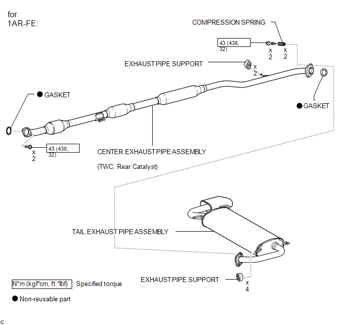
ILLUSTRATION
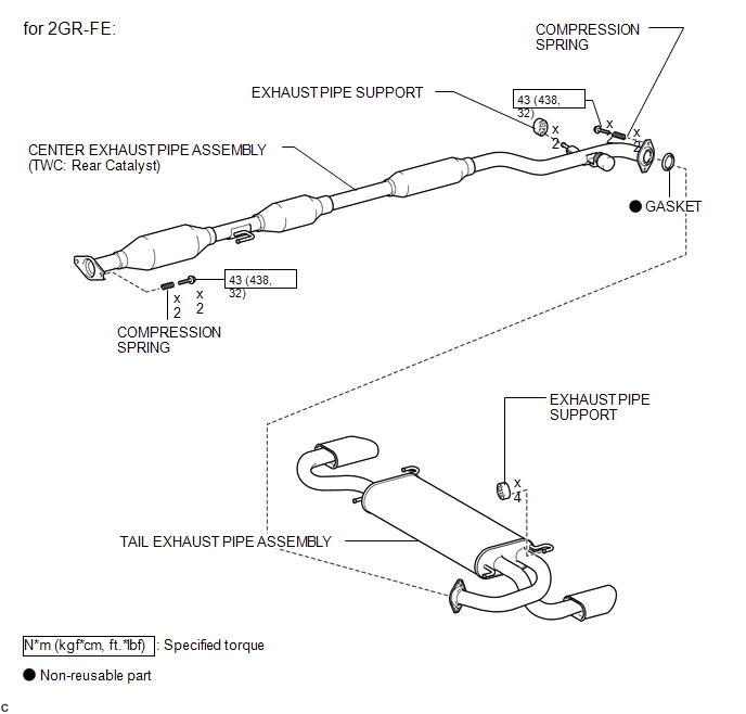
ILLUSTRATION
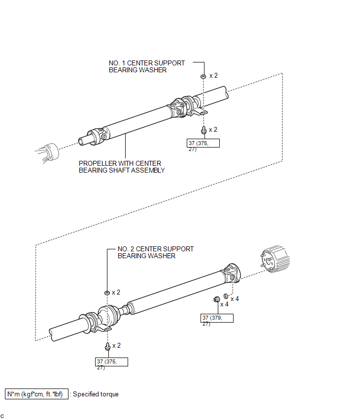
ILLUSTRATION
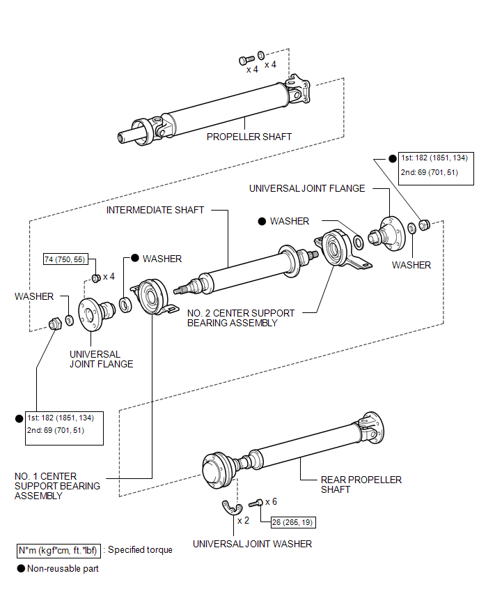
ILLUSTRATION

 Removal
REMOVAL
PROCEDURE
1. REMOVE TAIL EXHAUST PIPE ASSEMBLY (for 1AR-FE)
2. REMOVE TAIL EXHAUST PIPE ASSEMBLY (for 2GR-FE)
3. REMOVE CENTER EXHAUST PIPE ASSEMBLY (for 1AR-FE)
4. REMOVE CENTER ...
Other materials about Toyota Venza:
Pressure Control Solenoid "A" Performance (Shift Solenoid Valve SL1) (P0746)
SYSTEM DESCRIPTION
The TCM uses the vehicle speed signal and signals from the transmission speed
sensors (NC, NT) to detect the actual gear (1st, 2nd, 3rd, 4th, 5th or 6th gear).
Then the TCM compares the actual gear with the shift schedule in the TCM memo ...
Installation
INSTALLATION
PROCEDURE
1. INSTALL BRAKE MASTER CYLINDER SUB-ASSEMBLY
NOTICE:
When install a new brake master cylinder sub-assembly, remove the protectors
from the piston and outlet ports.
(a) Install a new O-ring to the brake master cylinder sub-assembl ...
Data List / Active Test
DATA LIST / ACTIVE TEST
1. DATA LIST
HINT:
Using the Techstream to read the Data List allows the values or states of switches,
sensors, actuators and other items to be read without removing any parts. This non-intrusive
inspection can be very useful bec ...

0.1163