Toyota Venza: Removal
REMOVAL
CAUTION / NOTICE / HINT
HINT:
- Use the same procedure for the LH side and RH side.
- The following procedure is for the LH side.
- If the sensor rotor needs to be replaced, replace it together with the rear drive shaft assembly.
PROCEDURE
1. DISCONNECT CABLE FROM NEGATIVE BATTERY TERMINAL
NOTICE:
When disconnecting the cable, some systems need to be initialized after the cable
is reconnected (See page .gif) ).
).
2. REMOVE REAR WHEEL
3. REMOVE REAR DOOR SCUFF PLATE LH
4. REMOVE REAR DOOR OPENING TRIM WEATHERSTRIP LH
5. REMOVE TONNEAU COVER ASSEMBLY (w/ Tonneau Cover)
6. REMOVE DECK BOARD ASSEMBLY
7. REMOVE NO. 3 DECK BOARD SUB-ASSEMBLY
8. REMOVE DECK SIDE TRIM BOX LH
9. REMOVE NO. 2 DECK BOARD SUB-ASSEMBLY
10. REMOVE DECK SIDE TRIM BOX RH
11. REMOVE NO. 1 DECK BOARD
12. REMOVE REAR SEAT SUB FLOOR PANEL ASSEMBLY
13. REMOVE REAR FLOOR FINISH PLATE
14. REMOVE RECLINING REMOTE CONTROL BEZEL LH
15. REMOVE LUGGAGE HOLD BELT STRIKER ASSEMBLY
16. DISCONNECT REAR SEAT OUTER BELT ASSEMBLY LH
17. REMOVE DECK TRIM SIDE PANEL ASSEMBLY LH
18. REMOVE REAR SPEED SENSOR
|
(a) Disconnect the rear speed sensor connector. Text in Illustration
|
|
.png)
|
(b) Disconnect the grommet of the rear speed sensor wire from the hole of the wheel house. Text in Illustration
|
|
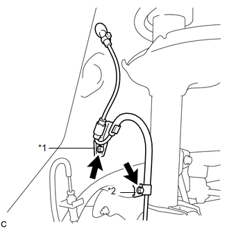
(c) Remove the 2 bolts, No. 1 clamp and No. 2 clamp from the body and absorber.
|
(d) Remove the bolt and rear speed sensor from the carrier. NOTICE: Keep the sensor tip and rear speed sensor installation hole free from foreign matter. |
|
.png)
 Installation
INSTALLATION
CAUTION / NOTICE / HINT
HINT:
Use the same procedure for the LH side and RH side.
The following procedure is for the LH side.
If the sensor rotor needs to be replaced, ...
 Relay
Relay
On-vehicle Inspection
ON-VEHICLE INSPECTION
PROCEDURE
1. REMOVE STOP LIGHT CONTROL (BRK) RELAY
(a) Remove the stop light control (BRK) relay.
(b) Measure the resistance according to ...
Other materials about Toyota Venza:
Precaution
PRECAUTION
1. PRECAUTION FOR DISCONNECTING CABLE FROM NEGATIVE BATTERY TERMINAL
NOTICE:
When disconnecting the cable from the negative (-) battery terminal, initialize
the following system after the cable is reconnected.
System Name
...
Check For Intermittent Problems
CHECK FOR INTERMITTENT PROBLEMS
1. CHECK FOR INTERMITTENT PROBLEMS
HINT:
A momentary interruption (open circuit) in the connectors and/or wire harness
between the sensors and ECUs can be detected using the ECU Data List function of
the Techstream.
(a) ...
Display does not Dim when Light Control Switch is Turned ON
PROCEDURE
1.
CHECK IMAGE QUALITY SETTING
(a) Turn the light control switch to the tail or head position.
(b) Check that the daytime screen setting on the display adjustment screen is
set to on.
Result
...

0.1186