Toyota Venza: Installation
INSTALLATION
CAUTION / NOTICE / HINT
HINT:
- Use the same procedure for the LH side and RH side.
- The following procedure is for the LH side.
- If the sensor rotor needs to be replaced, replace it together with the rear drive shaft assembly.
PROCEDURE
1. INSTALL REAR SPEED SENSOR
|
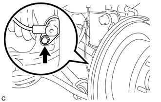
(a) Install the rear speed sensor with the bolt. Torque: 8.5 N·m {87 kgf·cm, 75 in·lbf} NOTICE:
|
|
|
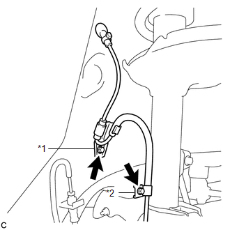
(b) Install the No. 1 clamp and No. 2 clamp with the 2 bolts. Torque: 8.0 N·m {82 kgf·cm, 71 in·lbf} NOTICE: Do not twist the rear speed sensor wire when installing the clamps. Text in Illustration
|
|
(c) Insert the connector and grommet to the inside of the vehicle through the passage hole in the wheel well.
NOTICE:
Make sure that the grommet's band clamp remains on the outside of the vehicle.
(d) Hold the grommet and pull it from the inside to the outside of the vehicle. Then secure it in place so that it is not tilted.
NOTICE:
When pulling out the grommet, do not grip the sensor wire.
|
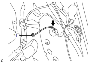
(e) Connect the rear speed sensor connector. Text in Illustration
|
|
2. INSTALL DECK TRIM SIDE PANEL ASSEMBLY LH
.gif)
3. CONNECT REAR SEAT OUTER BELT ASSEMBLY LH
4. INSTALL LUGGAGE HOLD BELT STRIKER ASSEMBLY
5. INSTALL RECLINING REMOTE CONTROL BEZEL LH
6. INSTALL REAR FLOOR FINISH PLATE
7. INSTALL REAR SEAT SUB FLOOR PANEL ASSEMBLY
8. INSTALL NO. 1 DECK BOARD
9. INSTALL DECK SIDE TRIM BOX RH
10. INSTALL NO. 2 DECK BOARD SUB-ASSEMBLY
11. INSTALL DECK SIDE TRIM BOX LH
12. INSTALL NO. 3 DECK BOARD SUB-ASSEMBLY
13. INSTALL DECK BOARD ASSEMBLY
14. INSTALL TONNEAU COVER ASSEMBLY (w/ Tonneau Cover)
15. INSTALL REAR DOOR OPENING TRIM WEATHERSTRIP LH
16. INSTALL REAR DOOR SCUFF PLATE LH
17. CONNECT CABLE TO NEGATIVE BATTERY TERMINAL
NOTICE:
When disconnecting the cable, some systems need to be initialized after the cable
is reconnected (See page ).
18. CHECK FOR SPEED SENSOR SIGNAL
HINT:
(See page ).
 Components
COMPONENTS
ILLUSTRATION
ILLUSTRATION
ILLUSTRATION
...
 Removal
REMOVAL
CAUTION / NOTICE / HINT
HINT:
Use the same procedure for the LH side and RH side.
The following procedure is for the LH side.
If the sensor rotor needs to be replaced, repla ...
Other materials about Toyota Venza:
Customize Parameters
CUSTOMIZE PARAMETERS
1. CUSTOMIZING FUNCTION WITH TECHSTREAM (REFERENCE)
HINT:
The following items can be customized.
NOTICE:
When the customer requests a change in a function, first make sure that
the function can be customized.
Record th ...
Propeller Shaft System
Problem Symptoms Table
PROBLEM SYMPTOMS TABLE
HINT:
Use the table below to help determine the cause of problem symptoms. If multiple
suspected areas are listed, the potential causes of the symptoms are listed in order
of probability in the "Suspe ...
Tongue Plate Stopper
Components
COMPONENTS
ILLUSTRATION
Replacement
REPLACEMENT
PROCEDURE
1. REMOVE TONGUE PLATE STOPPER
(a) Slide the tongue plate above the installation position of the tongue
plate stopper, and temporarily hold it with adhesive tape.
...

0.1594