Toyota Venza: Radio Antenna Pole
Components
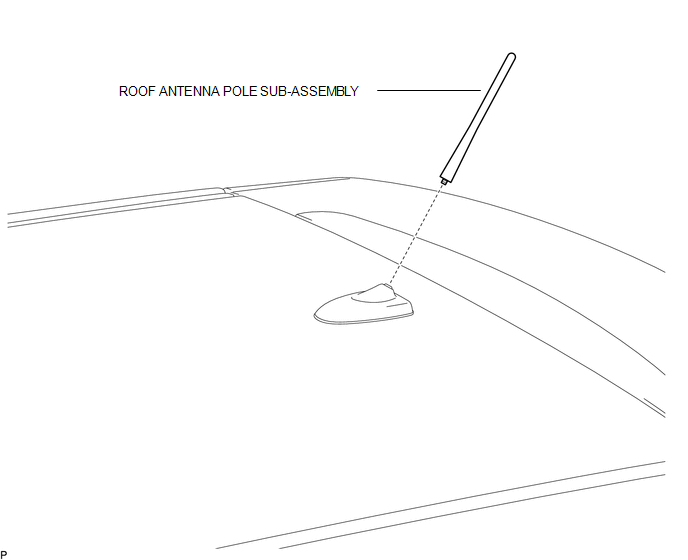
COMPONENTS
ILLUSTRATION
Removal
REMOVAL
PROCEDURE
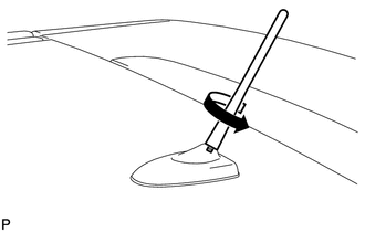
1. REMOVE ROOF ANTENNA POLE SUB-ASSEMBLY
|
(a) Turn the roof antenna pole sub-assembly in the direction indicated by the arrow in the illustration to remove it. |
|
Installation
INSTALLATION
PROCEDURE
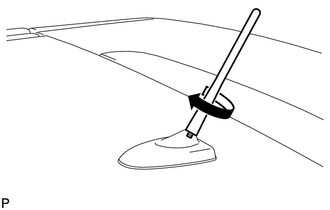
1. INSTALL ROOF ANTENNA POLE SUB-ASSEMBLY
|
(a) Turn the roof antenna pole sub-assembly in the direction indicated by the arrow in the illustration to install it. |
|
 Installation
INSTALLATION
PROCEDURE
1. INSTALL NO. 3 ANTENNA CORD SUB-ASSEMBLY
(a) Pass the washer hose through the No. 3 antenna cord sub-assembly.
(b) Pass the No. 3 antenna cord sub-assembly with ...
 Radio Receiver
...
Other materials about Toyota Venza:
Check Mode Procedure
CHECK MODE PROCEDURE
HINT:
Techstream only:
Compared to normal mode, check mode is more sensitive to malfunctions. Therefore,
check mode can detect malfunctions that cannot be detected in normal mode.
NOTICE:
All the stored DTCs and freeze frame data ar ...
Installation
INSTALLATION
PROCEDURE
1. INSTALL ROOF HEADLINING ASSEMBLY (w/o Sliding Roof)
(a) Pull the roof headlining assembly into the vehicle through the back
door.
NOTICE:
Do not damage the roof headlining assembly or body interior.
...
Removal
REMOVAL
PROCEDURE
1. REMOVE FRONT SEAT HEADREST ASSEMBLY
2. REMOVE FRONT SEAT REAR OUTER TRACK COVER
3. REMOVE FRONT SEAT REAR INNER TRACK COVER
4. REMOVE FRONT SEAT ASSEMBLY
5. REMOVE RECLINING POWER SEAT SWITCH KNOB
6. REMOVE SLIDE AND VER ...

0.1182