
Toyota Venza: Components
COMPONENTS
ILLUSTRATION
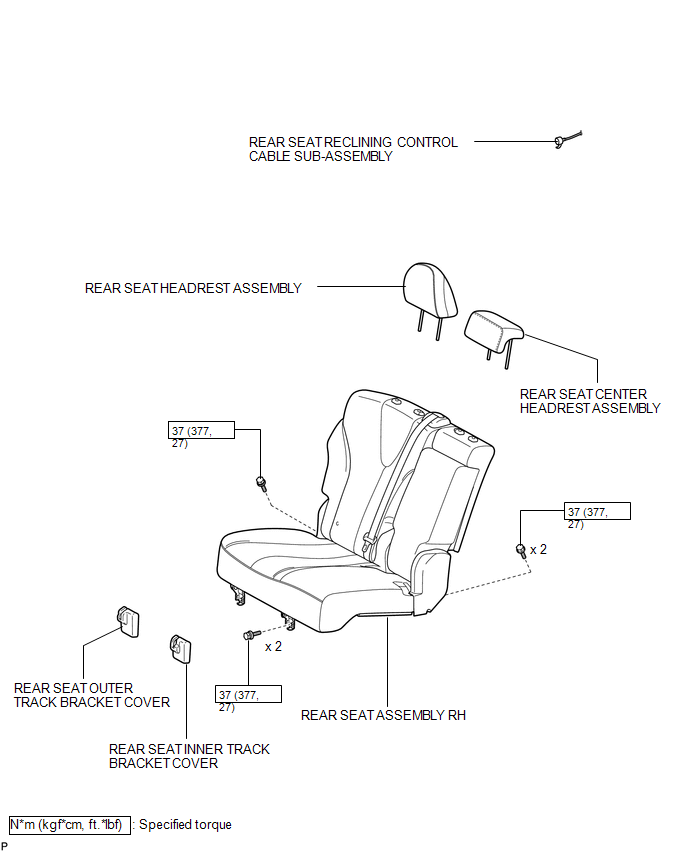
ILLUSTRATION
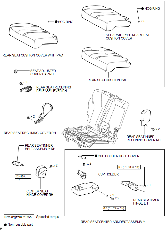
ILLUSTRATION
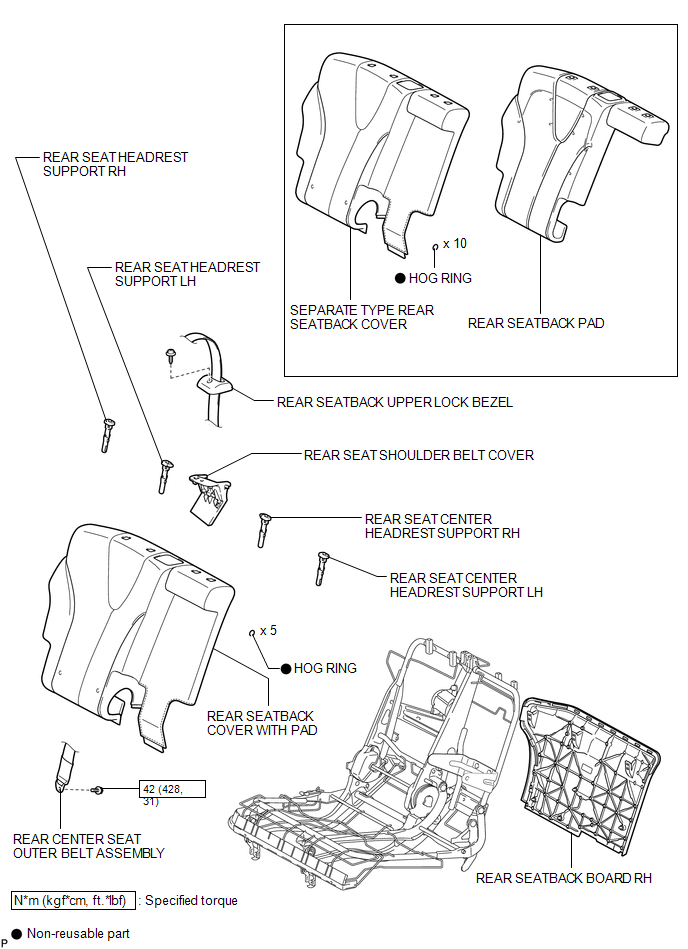
ILLUSTRATION
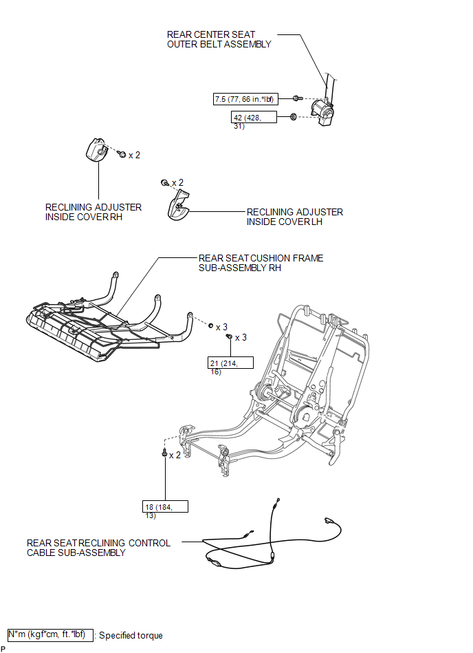
ILLUSTRATION
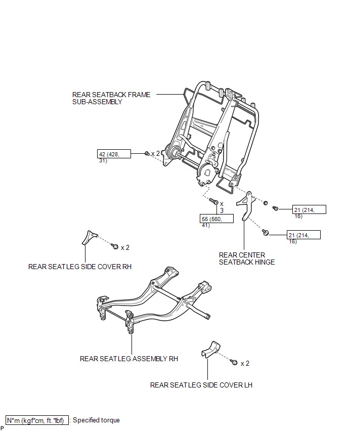

 Removal
REMOVAL
PROCEDURE
1. REMOVE REAR SEAT HEADREST ASSEMBLY
(a) Press the headrest support button and pull up the rear seat headrest
assembly as shown in the illustration.
...
Other materials about Toyota Venza:
Precaution
PRECAUTION
NOTICE:
When disconnecting the cable from the negative (-) battery terminal, initialize
the following systems after the cable is reconnected.
System Name
See Procedure
Back Door Closer System
...
ACC Monitor Malfunction (B2274)
DESCRIPTION
This DTC is stored when there is a problem in the ACC output circuit. The ACC
circuit is the circuit that goes from inside the power management control ECU to
the ACC relay.
DTC No.
DTC Detection Condition
Tro ...
ACIS Control Circuit
DESCRIPTION
This circuit opens and closes the Intake Air Control Valve (IACV) in response
to the engine load in order to increase the intake efficiency (ACIS: Acoustic Control
Induction System).
WIRING DIAGRAM
CAUTION / NOTICE / HINT
NOTICE:
Inspe ...

0.1884