Toyota Venza: ECM / PCM Internal Engine Off Timer Performance (P2610)
DTC SUMMARY
|
DTC No. |
Monitoring Item |
Malfunction Detection Condition |
Trouble Area |
Detection Timing |
Detection Logic |
|---|---|---|---|---|---|
|
P2610 |
Soak timer (built into ECM) |
An ECM internal malfunction. |
ECM |
Ignition switch off |
2 trip |
DESCRIPTION
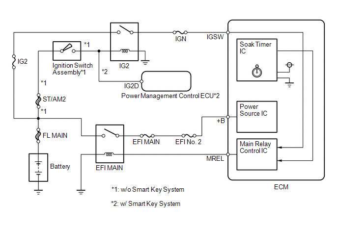
The soak timer operates after the ignition switch is turned off. When a certain amount of time has elapsed after turning the ignition switch off, the soak timer activates the ECM to perform malfunction checks which can only be performed after the engine is stopped. The soak timer is built into the ECM.
MONITOR DESCRIPTION
If the soak timer activates the ECM even though only a short amount of time has elapsed since the ignition switch was turned off, or if the soak timer does not activate the ECM even though a considerable amount of time has elapsed since the ignition switch was turned off, the ECM determines that the soak timer is malfunctioning, illuminates the MIL and stores a DTC the next time the ignition switch is turned ON.
MONITOR STRATEGY
|
Related DTC |
P2610: ECM internal engine off timer performance |
|
Required Sensors/Components |
ECM |
|
Frequency of Operation |
Once per driving cycle |
|
Duration |
2 time: Case 1 -: Case 2 and 3 |
|
MIL Operation |
2 driving cycles |
|
Sequence of Operation |
None |
TYPICAL ENABLING CONDITIONS
All|
Monitor runs whenever following DTC not stored |
None |
|
All of the following conditions are met |
- |
|
Ignition switch |
Off |
|
Battery voltage |
8 V or higher |
|
CPU clock elapsed time |
1.96608 seconds minutes or more |
|
All of the following conditions are met |
- |
|
Internal engine off timer (elapsed time from engine stop) |
10 minutes or more, and less than 30 minutes |
|
Battery voltage |
8 V or higher |
|
Ignition switch |
ON |
|
Starter |
Off |
|
All of the following conditions are met |
- |
|
Internal engine off timer (elapsed time from engine stop) |
40 minutes or more |
|
Battery voltage |
8 V or higher |
|
Ignition switch |
ON |
|
Starter |
Off |
TYPICAL MALFUNCTION THRESHOLDS
Case 1:|
One of the following conditions is met |
Condition A, B or C |
|
A. Both of the following conditions are met |
Condition (a) and (b) |
|
(a) CPU clock elapsed time |
1.96608 seconds or more, and less than 8.323072 seconds |
|
(b) Internal engine off timer |
9.375 seconds or more |
|
B. Both of the following conditions are met |
Condition (c) and (d) |
|
(c) CPU clock elapsed time |
8.323072 to 10.420224 seconds |
|
(d) Internal engine off timer |
18.75 seconds or more |
|
C. Both of the following conditions are met |
Condition (e) and (f) |
|
(e) CPU clock elapsed time |
More than 10.420224 seconds |
|
(f) Internal engine off timer |
Less than 9.375 seconds |
|
ECM started by internal engine off timer last trip |
Yes |
|
ECM started by internal engine off timer last trip |
No |
CONFIRMATION DRIVING PATTERN
- Connect the Techstream to the DLC3.
- Turn the ignition switch to ON and turn the Techstream on.
- Clear the DTCs (even if no DTCs are stored, perform the clear DTC procedure).
- Turn the ignition switch off and wait for at least 30 seconds.
- Start the engine and warm it up.
- Turn the ignition switch off and wait for at least 15 seconds.
- Start the engine.
- Stop the engine and leave the vehicle for 60 minutes or more.
- Turn the ignition switch to ON and turn the Techstream on.
- Enter the following menus: Powertrain / Engine / Trouble Codes.
- Read the pending DTCs.
HINT:
- If a pending DTC is output, the system is malfunctioning.
- If a pending DTC is not output, perform the following procedure.
- Enter the following menus: Powertrain / Engine / Utility / All Readiness.
- Input the DTC: P2610.
- Check the DTC judgment result.
Techstream Display
Description
NORMAL
- DTC judgment completed
- System normal
ABNORMAL
- DTC judgment completed
- System abnormal
INCOMPLETE
- DTC judgment not completed
- Perform driving pattern after confirming DTC enabling conditions
N/A
- Unable to perform DTC judgment
- Number of DTCs which do not fulfill DTC preconditions has reached ECU memory limit
HINT:
- If the judgment result shows NORMAL, the system is normal.
- If the judgment result shows ABNORMAL, the system has a malfunction.
- If the judgment result is INCOMPLETE or N/A and no pending DTC is output,
perform a universal trip and check for permanent DTCs (See page
.gif) ).
).
HINT:
- If a permanent DTC is output, the system is malfunctioning.
- If no permanent DTC is output, the system is normal.
CAUTION / NOTICE / HINT
HINT:
- DTC P2610 is stored if an internal ECM problem is detected. Diagnostic procedures are not required. ECM replacement is necessary.
- Read freeze frame data using the Techstream. The ECM records vehicle and driving condition information as freeze frame data the moment a DTC is stored. When troubleshooting, freeze frame data can help determine if the vehicle was moving or stationary, if the engine was warmed up or not, if the air fuel ratio was lean or rich, and other data from the time the malfunction occurred.
PROCEDURE
|
1. |
REPLACE ECM |
(a) Replace the ECM (See page ).
|
.gif)
|
2. |
CHECK WHETHER DTC OUTPUT RECURS (DTC P2610) |
(a) Connect the Techstream to the DLC3.
(b) Turn the ignition switch to ON.
(c) Turn the Techstream on.
(d) Clear the DTCs (See page ).
(e) Turn the ignition switch off and wait for at least 30 seconds.
(f) Turn the ignition switch to ON.
(g) Turn the Techstream on.
(h) Drive the vehicle in accordance with the driving pattern described in the Confirmation Driving Pattern.
(i) Enter the following menus: Powertrain / Engine / Trouble Codes / Pending.
(j) If no pending DTC is displayed, the repair has been successfully completed.
| NEXT | .gif) |
END |
 Evaporative Emission System Switching Valve Control Circuit High (P2420)
DTC SUMMARY
DTC No.
Monitoring Item
Malfunction Detection Condition
Trouble Area
Detection Timing
Detection Logic
P2 ...
 Lost Communication with TCM (U0101)
DESCRIPTION
The Transmission Control Module (TCM) and ECM perform 2-way communication with
each other via the Controller Area Network (CAN). The TCM sends signals to the ECM
concerning required e ...
Other materials about Toyota Venza:
On-vehicle Inspection
ON-VEHICLE INSPECTION
PROCEDURE
1. INSPECT GARAGE DOOR OPENER
(a) To inspect the garage door opener system, press each switch and check
that the LED in the "HomeLink" logo illuminates as illustrated. If one or
more of the switch ...
Reassembly
REASSEMBLY
PROCEDURE
1. INSTALL NO. 1 REAR BUMPER REINFORCEMENT
(a) Install the No. 1 rear bumper reinforcement with the 6 nuts.
Torque:
68 N·m {693 kgf·cm, 50 ft·lbf}
2. INSTALL REAR BUMP ...
Removal
REMOVAL
PROCEDURE
1. DISCONNECT CABLE FROM NEGATIVE BATTERY TERMINAL
CAUTION:
Wait at least 90 seconds after disconnecting the cable from the negative (-)
battery terminal to disable the SRS system (See page
).
NOTICE:
When disconnecting the cable, s ...

0.1321