Toyota Venza: Removal
REMOVAL
PROCEDURE
1. REMOVE FRONT SEAT HEADREST ASSEMBLY
2. REMOVE FRONT SEAT REAR OUTER TRACK COVER
.gif)
3. REMOVE FRONT SEAT REAR INNER TRACK COVER
4. REMOVE FRONT SEAT ASSEMBLY
5. REMOVE RECLINING POWER SEAT SWITCH KNOB
6. REMOVE SLIDE AND VERTICAL POWER SEAT SWITCH KNOB
7. REMOVE FRONT SEAT CUSHION SHIELD ASSEMBLY
8. REMOVE FRONT INNER SEAT CUSHION SHIELD
9. REMOVE POWER SEAT SWITCH
10. REMOVE FRONT SEAT INNER BELT ASSEMBLY
11. REMOVE SEPARATE TYPE FRONT SEAT CUSHION COVER WITH PAD
12. REMOVE FRONT SEATBACK BOARD SUB-ASSEMBLY
13. REMOVE SEPARATE TYPE FRONT SEATBACK COVER WITH PAD
14. REMOVE SEPARATE TYPE FRONT SEATBACK COVER
(a) Remove the 10 hog rings and the separate type front seatback cover.
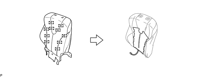
|
(b) Cut off the 12 tack pins that fasten the seat heater, and then remove the separate type front seatback heater from the front separate type seatback cover. |
|
.png)
 Components
COMPONENTS
ILLUSTRATION
ILLUSTRATION
ILLUSTRATION
...
 Inspection
INSPECTION
PROCEDURE
1. INSPECT FRONT SEATBACK HEATER LH
(a) Apply battery voltage and check the seatback heater.
OK:
Measurement Connection
Cond ...
Other materials about Toyota Venza:
Windshield Deicer does not Operate
DESCRIPTION
When the rear window defogger switch on the air conditioning control assembly
is pressed, the operation signal is transmitted to the air conditioning amplifier
assembly through the LIN communication line. When the air conditioning amplifier
...
Certification Ecu
Components
COMPONENTS
ILLUSTRATION
Removal
REMOVAL
PROCEDURE
1. DISCONNECT CABLE FROM NEGATIVE BATTERY TERMINAL
CAUTION:
Wait at least 90 seconds after disconnecting the cable from the negative (-)
battery terminal to disable the SRS system.
N ...
A/C ECU Vehicle Information Reading/Writing Processor Malfunction (B15F5)
DESCRIPTION
This DTC is stored when items controlled by the air conditioning amplifier assembly
cannot be customized via the navigation system vehicle customization screen.
HINT:
The air conditioning amplifier assembly controls the air conditioning system ...

0.1499