Toyota Venza: Components
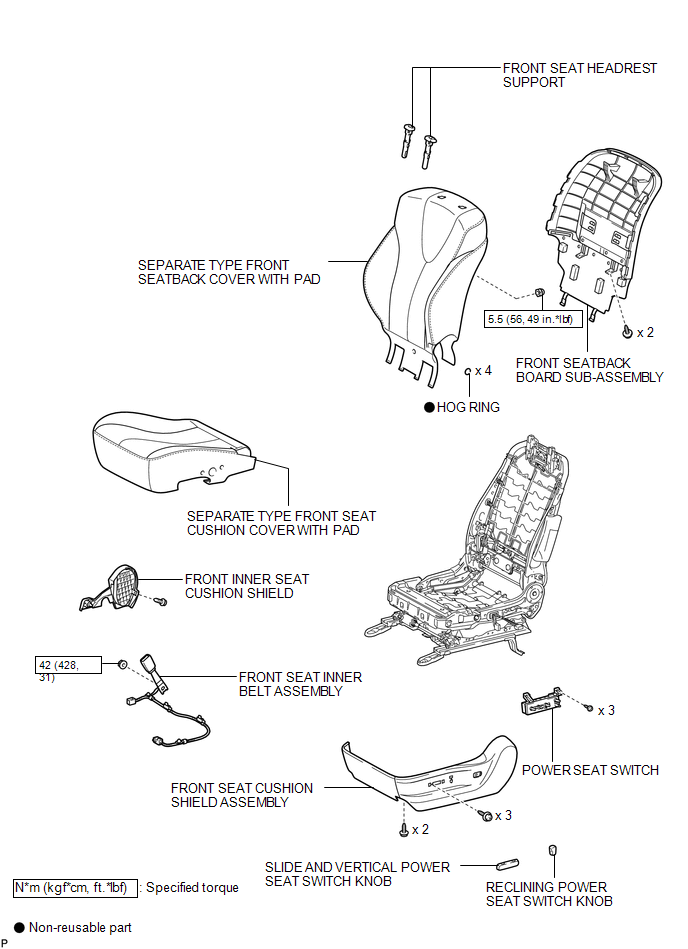
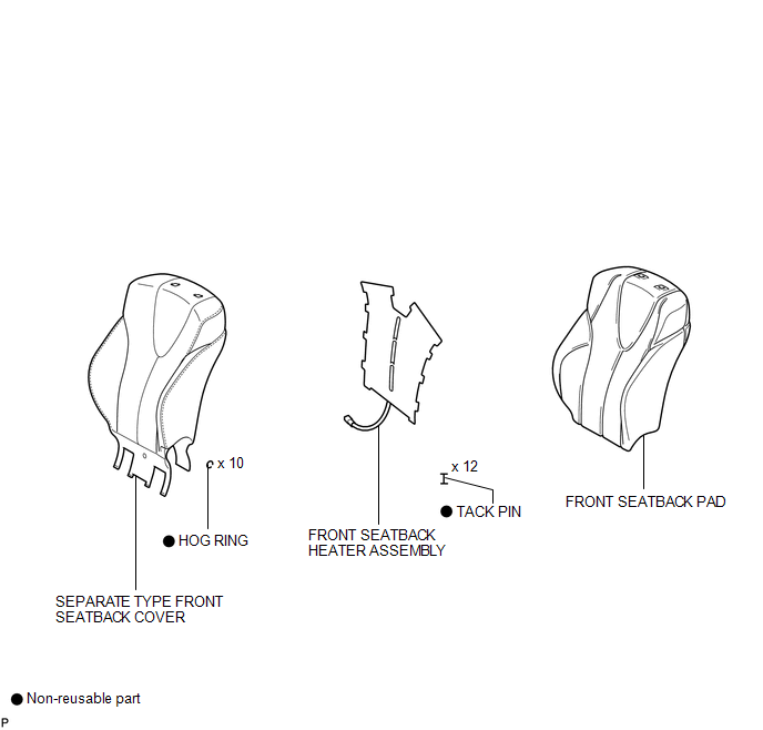
COMPONENTS
ILLUSTRATION
.png)
ILLUSTRATION
ILLUSTRATION

 Removal
REMOVAL
PROCEDURE
1. REMOVE FRONT SEAT HEADREST ASSEMBLY
2. REMOVE FRONT SEAT REAR OUTER TRACK COVER
3. REMOVE FRONT SEAT REAR INNER TRACK COVER
4. REMOVE FRONT SEAT ASSEMBLY
5. REMOVE ...
Other materials about Toyota Venza:
Check CAN Bus Line for Short to +B
DESCRIPTION
There may be a short circuit between the CAN bus main wire and +B when no resistance
exists between terminals 6 (CANH) and 16 (BAT) or 14 (CANL) and 16 (BAT) of the
DLC3.
Symptom
Trouble Area
No resistan ...
Problem Symptoms Table
PROBLEM SYMPTOMS TABLE
HINT:
Use the table below to help determine the cause of problem symptoms.
If multiple suspected areas are listed, the potential causes of the symptoms
are listed in order of probability in the "Suspected Area" ...
Key information
Keys
The following keys are provided with the vehicle.
►Vehicles with smart key system
1. Electronic keys
• Operating the smart key system
• Operating the wireless remote control function
2. Mechanical keys
3. Key number plate
►Veh ...

0.1582