Toyota Venza: Terminals Of Ecu
TERMINALS OF ECU
1. CHECK MAIN BODY ECU (DRIVER SIDE JUNCTION BLOCK ASSEMBLY)
(a) Disconnect the 2A, 2C and 2F main body ECU (driver side junction block assembly) connectors.
.png)
(b) Measure the voltage and resistance according to the value(s) in the table below.
HINT:
Measure the values on the wire harness side with the connector disconnected.
|
Symbols (Terminal No.) |
Wiring Color |
Terminal Description |
Condition |
Specified Condition |
|---|---|---|---|---|
|
2A-1 (IG) - Body ground |
B - Body ground |
Ignition power supply (IG signal) |
Engine switch on (IG) → off |
10 to 14 V → Below 1 V |
|
2A-1 (ACC) - Body ground |
B - Body ground |
Ignition power supply (ACC signal) |
Engine switch on (ACC) → off |
10 to 14 V → Below 1 V |
|
2C-30 (ALTB) - Body ground |
BR - Body ground |
+B (power system alternator system) power supply |
Always |
10 to 14 V |
|
2F-16 (GND1) - Body ground |
W-B - Body ground |
Ground |
Always |
Below 1 Ω |
If the result is not as specified, there may be a malfunction on the wire harness side.
(c) Reconnect the 2A, 2C and 2F main body ECU (driver side junction block assembly) connectors.
(d) Measure the voltage according to the value(s) in the table below.
|
Symbols (Terminal No.) |
Wiring Color |
Terminal Description |
Condition |
Specified Condition |
|---|---|---|---|---|
|
D50-24 (DCTY) - Body ground |
V - Body ground |
Driver side door courtesy light switch input |
Driver side door CLOSED (OFF) → OPEN (ON) |
Pulse generation → Below 1 V |
|
D49-21 (PCTY) - Body ground |
V - Body ground |
Passenger side courtesy light switch input |
Passenger side door CLOSED (OFF) → OPEN (ON) |
Pulse generation → Below 1 V |
|
D49-7 (RCTY) - Body ground |
GR - Body ground |
Rear courtesy light switch RH input |
Rear door RH CLOSED (OFF) → OPEN (ON) |
Pulse generation → Below 1 V |
|
2O-19 (LCTY) - Body ground |
R - Body ground |
Rear courtesy light switch LH input |
Rear door LH CLOSED (OFF) → OPEN (ON) |
Pulse generation → Below 1 V |
|
D49-25 (BCTY) - Body ground |
GR - Body ground |
Back door courtesy light switch input |
Back door CLOSED (OFF) → OPEN (ON) |
Pulse generation → Below 1 V |
|
D48-4 (HAZ) - Body ground |
G - Body ground |
Turn signal flasher relay signal |
Any transmitter switch is pressed → not pressed |
Below 1 V → 10 to 14 V |
|
2C-25 (HORN) - Body ground |
R - Body ground |
Vehicle horn siganal |
Vehicle horn is sounding (Panic alarm system is in alarm sounding state) |
Below 1 V → 12 V |
|
D51-7 (BZR) - Body ground |
LG - Body ground |
Wireless door lock buzzer signal |
Wireless door lock buzzer OFF → ON |
Below 1 V → Pulse generation |
If the result is not as specified, the main body ECU (driver side junction block assembly) may have a malfunction.
2. CHECK CERTIFICATION ECU (SMART KEY ECU ASSEMBLY)
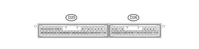
(a) Disconnect the D25 and D26 certification ECU (smart key ECU assembly) connectors.
(b) Measure the resistance and voltage according to the value(s) in the table below.
|
Terminal No. (Symbols) |
Wiring Color |
Terminal Description |
Condition |
Specified Condition |
|---|---|---|---|---|
|
D25-15 (E) - Body ground |
B - Body ground |
Ground |
Always |
Below 1 Ω |
|
D25-1 (+B) - D25-15 (E) |
G - B |
Battery power supply |
Always |
11 to 14 V |
|
D25-16 (IG) - D25-15 (E) |
R - B |
IG power supply |
Engine switch on (IG) |
11 to 14 V |
|
Engine switch off |
Below 1 V |
- If the result is not as specified, there may be a malfunction on the wire harness side.
(c) Reconnect the D25 and D26 certification ECU (smart key ECU assembly) connectors.
(d) Measure the voltage according to the value(s) in the table below.
|
Terminal No. (Symbols) |
Wiring Color |
Terminal Description |
Condition |
Specified Condition |
|---|---|---|---|---|
|
D26-16 (RSSI) - D25-15 (E) |
P - B |
Door control receiver output signal |
Engine switch off, all doors closed and transmitter switch not pressed |
11 to 14 V |
|
Engine switch off, all doors closed and transmitter switch pressed |
Below 2 V |
|||
|
D26-15 (RDA) - D25-15 (E) |
R - B |
Door control receiver input signal |
Engine switch off, all doors closed and transmitter switch not pressed |
11 to 14 V pulse generation at regular intervals |
|
Engine switch off, all doors closed and transmitter switch pressed |
Pulse generation |
|||
|
D26-5 (RCO) - D25-15 (E) |
Y - B |
Supply battery to door control receiver |
Engine switch off, all doors closed and transmitter switch pressed |
4.5 to 5.5 V |
- If the result is not as specified, the certification ECU (smart key ECU assembly) may have a malfunction.
 Problem Symptoms Table
PROBLEM SYMPTOMS TABLE
HINT:
Use the table below to help determine the cause of problem symptoms.
If multiple suspected areas are listed, the potential causes of the symptoms
are lis ...
 Diagnosis System
DIAGNOSIS SYSTEM
1. DESCRIPTION
The ECU stores trouble codes when malfunctions occur.
The diagnostic system allows for reading of the trouble codes from the DLC3.
Use the Techstream to help diagno ...
Other materials about Toyota Venza:
Removal
REMOVAL
PROCEDURE
1. DISCONNECT FRONT DOOR OPENING TRIM WEATHERSTRIP
2. REMOVE FRONT PILLAR GARNISH
3. REMOVE NO. 2 INSTRUMENT PANEL SPEAKER PANEL SUB-ASSEMBLY
4. REMOVE FRONT NO. 4 SPEAKER ASSEMBLY (for 13 Speakers)
(a) Remove the 2 ...
Front Occupant Classification Sensor LH Circuit Malfunction (B1780)
DESCRIPTION
The front occupant classification sensor LH circuit consists of the occupant
classification ECU and front occupant classification sensor LH.
DTC B1780 is recorded when a malfunction is detected in the front occupant classification
sensor LH c ...
Problem Symptoms Table
PROBLEM SYMPTOMS TABLE
HINT:
Use the table below to help determine the cause of problem symptoms. If multiple
suspected areas are listed, the potential causes of the symptoms are listed in order
of probability in the "Suspected Area" column of ...

0.1648