Toyota Venza: Removal
REMOVAL
PROCEDURE
1. REMOVE FRONT SEAT HEADREST ASSEMBLY
2. REMOVE FRONT SEAT REAR OUTER TRACK COVER
.gif)
3. REMOVE FRONT SEAT REAR INNER TRACK COVER
4. REMOVE FRONT SEAT ASSEMBLY
5. REMOVE RECLINING POWER SEAT SWITCH KNOB
6. REMOVE SLIDE AND VERTICAL POWER SEAT SWITCH KNOB
7. REMOVE FRONT SEAT CUSHION SHIELD ASSEMBLY
8. REMOVE FRONT SEAT INNER BELT ASSEMBLY
9. REMOVE FRONT INNER SEAT CUSHION SHIELD
10. REMOVE POWER SEAT SWITCH
11. REMOVE SEPARATE TYPE FRONT SEAT CUSHION COVER WITH PAD
12. REMOVE SEPARATE TYPE FRONT SEAT CUSHION COVER
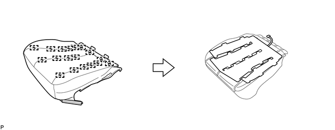
(a) Remove the 18 hog rings and the separate type front seat cushion cover.
|
(b) Cut off the 25 tack pins that fasten the seat heater, and then remove the separate type front seat cushion heater assembly from the separate type front seat cushion cover. |
|
.png)
 Components
COMPONENTS
ILLUSTRATION
ILLUSTRATION
ILLUSTRATION
...
 Inspection
INSPECTION
PROCEDURE
1. INSPECT FRONT SEAT CUSHION HEATER LH
(a) Check the seat cushion heater.
(1) Apply battery voltage and check the seat cushion heater.
OK:
...
Other materials about Toyota Venza:
Diagnostic Trouble Code Chart
DIAGNOSTIC TROUBLE CODE CHART
HINT:
If a trouble code is displayed during the DTC check, inspect the trouble areas
listed below for that code. For details of the code, refer to the following "See
page".
Power back door system
DTC C ...
Tire Pressure Warning Receiver
Components
COMPONENTS
ILLUSTRATION
Removal
REMOVAL
PROCEDURE
1. DISCONNECT CABLE FROM NEGATIVE BATTERY TERMINAL
NOTICE:
When disconnecting the cable, some systems need to be initialized after the cable
is reconnected (See page ).
2. REMOVE RO ...
System Voltage (P0560)
DESCRIPTION
The battery supplies electricity to the TCM even when the ignition switch is
off. This power allows the TCM to store data such as DTC history and freeze frame
data. If the battery voltage falls below a minimum level, these memories are cleared ...

0.1556