Toyota Venza: Inspection
INSPECTION
PROCEDURE
1. INSPECT FRONT SEAT CUSHION HEATER LH
|
(a) Check the seat cushion heater. (1) Apply battery voltage and check the seat cushion heater. OK:
If the result is not as specified, replace the seat cushion heater. NOTICE: Immediately after confirming that the seat heater is functioning normally, remove the battery leads. Failing to do so may cause the seat heater to overheat. |
|
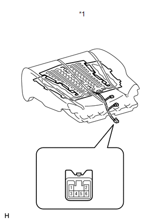
(b) Check the thermostat.
(1) Apply battery voltage and check the seat cushion heater.
OK:
|
Measurement Condition |
Condition |
Specified Condition |
|---|---|---|
|
Battery positive (+) → Terminal 4 Battery negative (-) → Terminal 6 |
Always |
Seat cushion heater temperature below 55°C (129°F) |
If the result is not as specified, replace the seat cushion heater.
NOTICE:
Immediately after confirming that the seat heater is functioning normally, remove the battery leads. Failing to do so may cause the seat heater to overheat.
 Removal
REMOVAL
PROCEDURE
1. REMOVE FRONT SEAT HEADREST ASSEMBLY
2. REMOVE FRONT SEAT REAR OUTER TRACK COVER
3. REMOVE FRONT SEAT REAR INNER TRACK COVER
4. REMOVE FRONT SEAT ASSEMBLY
5. REMOVE ...
 Installation
INSTALLATION
PROCEDURE
1. INSTALL SEPARATE TYPE FRONT SEAT CUSHION COVER
(a) Using a tacker, install the separate type front seat cushion heater
to the end of the separate type front ...
Other materials about Toyota Venza:
Reassembly
REASSEMBLY
CAUTION / NOTICE / HINT
HINT:
Use an overhaul stand as necessary.
PROCEDURE
1. INSTALL DIFFERENTIAL RING GEAR
(a) Clean the contact surfaces of the rear differential case sub-assembly and
differential ring gear.
(b) Heat the differential ri ...
Terminals Of Ecu
TERMINALS OF ECU
1. CHECK ENGINE SWITCH
(a) Disconnect the D13 engine switch connector.
(b) Measure the resistance according to the value(s) in the table below.
HINT:
Measure the values on the wire harness side with connector disconnected.
T ...
Television Camera
Components
COMPONENTS
ILLUSTRATION
ILLUSTRATION
Removal
REMOVAL
PROCEDURE
1. REMOVE BACK DOOR PANEL TRIM ASSEMBLY
2. REMOVE REAR WIPER ARM HEAD CAP
3. REMOVE REAR WIPER ARM AND BLADE ASSEMBLY
4. REMOVE REAR WIPER MOTOR GROMMET
5. ...

0.1614