Toyota Venza: Power Source Circuit
DESCRIPTION
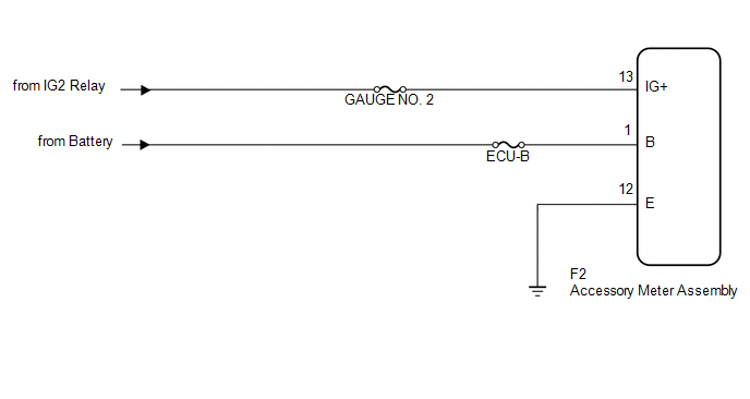
1. w/o Multi-information Display
(a) This circuit is the power source circuit for the accessory meter assembly. This circuit provides two types of power sources; one is a constant power source mainly used as a backup power source, and the other is a power source mainly used for signal transmission.
HINT:
If the accessory meter assembly displays "1:00" when the ignition switch is turned off, then to ON again, the B terminal has a malfunction.
The maximum clock assembly margin of error is -4 to 4 seconds per day when the temperature is between -20°C (-4°F) and 60°C (140°F).
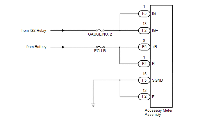
2. w/ Multi-information Display
(a) This circuit is the power source circuit for the accessory meter assembly. This circuit provides two types of power sources; one is a constant power source mainly used as a backup power source, and the other is a power source mainly used for signal transmission.
HINT:
If the accessory meter assembly displays "1:00" when the ignition switch is turned off, then to ON again, the +B terminal has a malfunction.
The maximum clock assembly margin of error is -4 to 4 seconds per day when the temperature is between -20°C (-4°F) and 60°C (140°F).
WIRING DIAGRAM
1. w/o Multi-information Display
2. w/ Multi-information Display
PROCEDURE
|
1. |
CHECK HARNESS AND CONNECTOR |
(a) w/o Multi-information Display
|
(1) Disconnect the F2 connector. |
|
(2) Measure the voltage according to the value(s) in the table below.
Standard Voltage:
|
Tester Connection |
Condition |
Specified Condition |
|---|---|---|
|
F2-1 (B) - Body ground |
Always |
11 to 14 V |
|
F2-13 (IG+) - Body ground |
Ignition switch ON |
11 to 14 V |
(3) Measure the resistance according to the value(s) in the table below.
Standard Resistance:
|
Tester Connection |
Condition |
Specified Condition |
|---|---|---|
|
F2-12 (E) - Body ground |
Always |
Below 1 Ω |
|
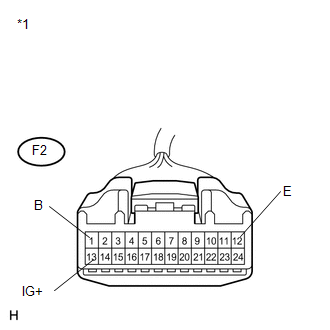
*1 |
Front view of wire harness connector (to Accessory Meter Assembly) |
(b) w/ Multi-information Display
|
(1) Disconnect the F2 and F5 connectors. |
|
(2) Measure the voltage according to the value(s) in the table below.
Standard Voltage:
|
Tester Connection |
Condition |
Specified Condition |
|---|---|---|
|
F5-1 (IG) - Body ground |
Ignition switch ON |
11 to 14 V |
|
F5-9 (+B) - Body ground |
Always |
11 to 14 V |
|
F2-1 (B) - Body ground |
Always |
11 to 14 V |
|
F2-13 (IG+) - Body ground |
Ignition switch ON |
11 to 14 V |
(3) Measure the resistance according to the value(s) in the table below.
Standard Resistance:
|
Tester Connection |
Condition |
Specified Condition |
|---|---|---|
|
F2-12 (E) - Body ground |
Always |
Below 1 Ω |
|
F5-16 (SGND) - Body ground |
Always |
Below 1 Ω |
|
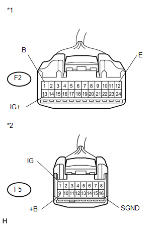
*1 |
Front view of wire harness connector (to Accessory Meter Assembly) |
|
*2 |
Front view of wire harness connector (to Accessory Meter Assembly ) |
| OK | .gif) |
REPLACE ACCESSORY METER ASSEMBLY |
| NG | |
REPAIR OR REPLACE HARNESS OR CONNECTOR |
 Speed Signal Circuit
DESCRIPTION
The combination meter assembly receives the vehicle speed signal from this circuit.
The wheel speed sensors produce an output that varies according to the vehicle speed.
The wheel spe ...
 Mirror (int)
...
Other materials about Toyota Venza:
Installation
INSTALLATION
PROCEDURE
1. INSTALL NO. 1 COOLER THERMISTOR
2. INSTALL COOLER EVAPORATOR SUB-ASSEMBLY
3. INSTALL BLOWER ASSEMBLY WITH COOLER EVAPORATOR SUB-ASSEMBLY
(a) Engage the 5 claws.
(b) Engage the guide and connect the wire harness.
(c) Insta ...
Front Stabilizer Bar(for 2gr-fe 2wd)
Components
COMPONENTS
ILLUSTRATION
Removal
REMOVAL
PROCEDURE
1. REMOVE FRONT FRAME ASSEMBLY (When Using the Engine Support Bridge)
(See page )
2. REMOVE ENGINE ASSEMBLY WITH TRANSAXLE (When Not Using the Engine Support Bridge)
(See page )
3. ...
Transfer Oil
On-vehicle Inspection
ON-VEHICLE INSPECTION
PROCEDURE
1. INSPECT TRANSFER OIL
(a) Remove the No. 1 transfer case plug and gasket.
(b) Check that the oil level is between 0 and 5 mm (0 ...

0.1597