Toyota Venza: Parking Brake Switch Circuit
DESCRIPTION
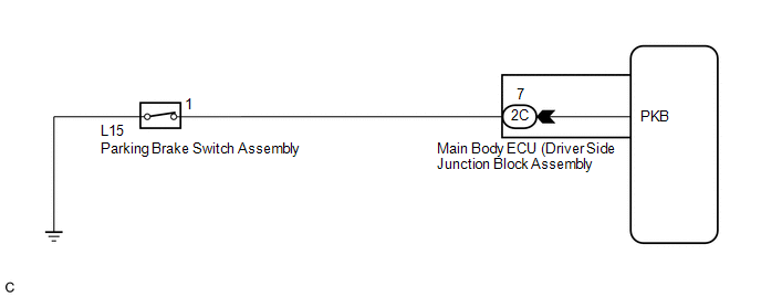
The main body ECU (driver side junction block assembly) detects the condition of the parking brake switch.
WIRING DIAGRAM
PROCEDURE
|
1. |
READ VALUE USING TECHSTREAM |
(a) Connect the Techstream to the DLC3.
(b) Turn the ignition switch to ON.
(c) Turn the Techstream on.
(d) Enter the following menus: Body Electrical / Main Body / Data List.
(e) Read the display on the Techstream.
Main Body|
Tester Display |
Measurement Item/Range |
Normal Condition |
Diagnostic Note |
|---|---|---|---|
|
Parking Brake SW |
Parking brake SW signal/ON or OFF |
ON: Parking brake switch on OFF: Parking brake switch off |
- |
OK:
Normal conditions listed above are displayed.
| OK | .gif) |
PROCEED TO NEXT SUSPECTED AREA SHOWN IN PROBLEM SYMPTOMS TABLE |
|
.gif)
|
2. |
INSPECT PARKING BRAKE SWITCH ASSEMBLY |
|
(a) Remove the parking brake switch assembly (See page
|
|
.gif) ).
).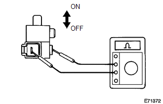
(b) Measure the resistance according to the value(s) in the table below.
Standard Resistance:
|
Tester Connection |
Condition |
Specified Condition |
|---|---|---|
|
1 - Switch body |
Shaft pushed in (OFF) |
10 kΩ or higher |
|
1 - Switch body |
Shaft not pushed in (ON) |
Below 1 Ω |
| NG | |
REPLACE PARKING BRAKE SWITCH ASSEMBLY |
|
|
3. |
CHECK HARNESS AND CONNECTOR (SWITCH - MAIN BODY ECU (DRIVER SIDE JUNCTION BLOCK ASSEMBLY)) |
|
(a) Disconnect the 2C main body ECU (driver side junction block assembly) connector. |
|
(b) Disconnect the L15 parking brake switch assembly connector.
(c) Measure the resistance according to the value(s) in the table below.
Standard Resistance:
|
Tester Connection |
Condition |
Specified Condition |
|---|---|---|
|
2C-7 - L15-1 |
Always |
Below 1 Ω |
|
2C-7 - Body ground |
Always |
10 kΩ or higher |
|
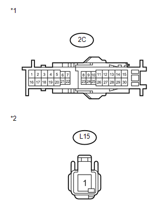
*1 |
Front view of wire harness connector: (to Main Body ECU (Driver Side Junction Block Assembly)) |
|
*2 |
Front view of wire harness connector (to Parking Brake Switch Assembly) |
| OK | |
REPLACE MAIN BODY ECU (DRIVER SIDE JUNCTION BLOCK ASSEMBLY) |
| NG | |
REPAIR OR REPLACE HARNESS OR CONNECTOR |
 Door Mirror Foot Light Circuit
DESCRIPTION
The main body ECU (driver side junction block assembly) controls the door mirror
foot lights.
WIRING DIAGRAM
1. w/o Seat Position Memory:
2. w/ Seat Position Memory:
PROCEDURE
...
 Taillight Relay Circuit
DESCRIPTION
The main body ECU (driver side junction block assembly) controls the operation
of the TAIL relay.
WIRING DIAGRAM
CAUTION / NOTICE / HINT
NOTICE:
Inspect the fuses for circuits rel ...
Other materials about Toyota Venza:
Adjustment
ADJUSTMENT
PROCEDURE
1. ADJUST PARK/NEUTRAL POSITION SWITCH ASSEMBLY
(a) Remove the transmission control shaft lever.
HINT:
See the steps from "Remove Cool Air Intake Duct Seal" through "Remove Park/Neutral
Position Switch Assembly" ...
On-vehicle Inspection
ON-VEHICLE INSPECTION
PROCEDURE
1. INSPECT DRIVER SIDE SEAT BELT WARNING
(a) Turn the ignition switch to ON.
(b) When the driver side seat belt is not fastened, check that the driver side
seat belt warning light on the combination meter assembly blinks.
...
On-vehicle Inspection
ON-VEHICLE INSPECTION
PROCEDURE
1. CHECK BATTERY CONDITION
NOTICE:
If the battery is weak or if the engine is difficult to start, perform the following
procedure.
(a) Check the battery for damage and deformation. If severe damage, deformation
or leaka ...

0.1723