Toyota Venza: Removal
REMOVAL
PROCEDURE
1. REMOVE FRONT DOOR SCUFF PLATE LH
.gif)
2. REMOVE COWL SIDE TRIM SUB-ASSEMBLY LH
3. REMOVE LOWER NO. 1 INSTRUMENT PANEL FINISH PANEL
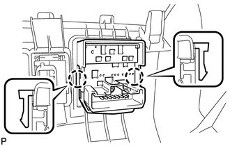
4. REMOVE OUTER MIRROR SWITCH ASSEMBLY
|
(a) Disengage the 2 claws and remove the outer mirror switch assembly. |
|
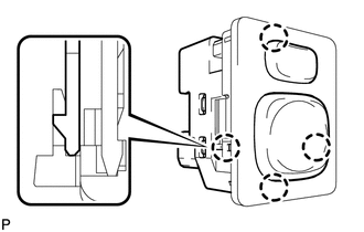
5. REMOVE OUTER MIRROR SWITCH
|
(a) Disengage the 4 claws and remove the outer mirror switch. |
|
 Components
COMPONENTS
ILLUSTRATION
...
 Inspection
INSPECTION
PROCEDURE
1. INSPECT OUTER MIRROR SWITCH ASSEMBLY (w/o Memory)
(a) The L position of the left/right adjustment switch: Measure the resistance
according to the value(s) in the table b ...
Other materials about Toyota Venza:
Engine Stall History (P1603,P1605)
DESCRIPTION
P1603
After starting the engine, this DTC is stored when the engine stops without the
ignition switch being operated.
Using the Techstream, the conditions present when the DTC was stored can be confirmed
by referring to the freeze frame data ...
Removal
REMOVAL
PROCEDURE
1. REMOVE REAR WHEELS
2. REMOVE CENTER EXHAUST PIPE ASSEMBLY
(a) Remove the center exhaust pipe assembly.
HINT:
Refer to the instructions for Removal of the exhaust pipe (See page
for 2GR-FE,
for 1AR-FE).
3. REMOVE PROPELLER WITH ...
Abbreviations Used In Manual
ABBREVIATIONS USED IN MANUAL
Abbreviation
Meaning
ABS
Anti-Lock Brake System
A/C
Air Conditioner
AC
Alternating Current
ACC
A ...

0.129