Toyota Venza: Inspection
INSPECTION
PROCEDURE
1. INSPECT OUTER MIRROR SWITCH ASSEMBLY (w/o Memory)
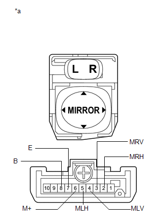
(a) The L position of the left/right adjustment switch: Measure the resistance according to the value(s) in the table below.
Standard Resistance (for Left Side):
|
Tester Connection |
Condition |
Specified Condition |
|---|---|---|
|
4 (MLV) - 8 (B) 6 (M+) - 7 (E) |
UP |
Below 1 Ω |
|
OFF |
10 kΩ or higher |
|
|
4 (MLV) - 7 (E) 6 (M+) - 8 (B) |
DOWN |
Below 1 Ω |
|
OFF |
10 kΩ or higher |
|
|
5 (MLH) - 8 (B) 6 (M+) - 7 (E) |
LEFT |
Below 1 Ω |
|
OFF |
10 kΩ or higher |
|
|
5 (MLH) - 7 (E) 6 (M+) - 8 (B) |
RIGHT |
Below 1 Ω |
|
OFF |
10 kΩ or higher |
|
*a |
Component without harness connected (Outer Mirror Switch Assembly) |
If the result is not as specified, replace the switch assembly.
(b) The R position of the left/right adjustment switch: Measure the resistance according to the value(s) in the table below.
Standard Resistance (for Right Side):
|
Tester Connection |
Condition |
Specified Condition |
|---|---|---|
|
3 (MRV) - 8 (B) 6 (M+) - 7 (E) |
UP |
Below 1 Ω |
|
OFF |
10 kΩ or higher |
|
|
3 (MRV) - 7 (E) 6 (M+) - 8 (B) |
DOWN |
Below 1 Ω |
|
OFF |
10 kΩ or higher |
|
|
2 (MRH) - 8 (B) 6 (M+) - 7 (E) |
LEFT |
Below 1 Ω |
|
OFF |
10 kΩ or higher |
|
|
2 (MRH) - 7 (E) 6 (M+) - 8 (B) |
RIGHT |
Below 1 Ω |
|
OFF |
10 kΩ or higher |
|
*a |
Component without harness connected (Outer Mirror Switch Assembly) |
If the result is not as specified, replace the switch assembly.
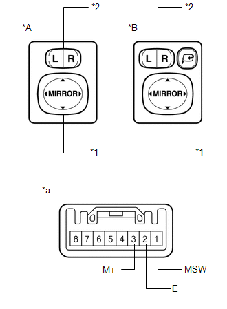
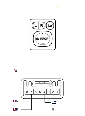
2. INSPECT OUTER MIRROR SWITCH ASSEMBLY (w/ Memory)
|
(a) Check the switch functions. (1) Measure the resistance according to the value(s) in the table below. Standard Resistance:
If the result is not as specified, replace the outer mirror switch assembly. |
|
(b) Check the mirror retract switch.
|
(1) Measure the resistance according to the value(s) in the table below. Standard Resistance:
If the result is not as specified, replace the outer mirror switch assembly. |
|
 Removal
REMOVAL
PROCEDURE
1. REMOVE FRONT DOOR SCUFF PLATE LH
2. REMOVE COWL SIDE TRIM SUB-ASSEMBLY LH
3. REMOVE LOWER NO. 1 INSTRUMENT PANEL FINISH PANEL
4. REMOVE OUTER MIRROR SWITCH ASSEMBLY
...
 Installation
INSTALLATION
PROCEDURE
1. INSTALL OUTER MIRROR SWITCH
(a) Engage the 4 claws to install the outer mirror switch.
2. INSTALL OUTER MIRROR S ...
Other materials about Toyota Venza:
Data List / Active Test
DATA LIST / ACTIVE TEST
1. DATA LIST
NOTICE:
In the table below, the values listed under "Normal Condition" are reference
values. Do not depend solely on these reference values when deciding whether a part
is faulty or not.
HINT:
Using the T ...
Reassembly
REASSEMBLY
PROCEDURE
1. INSTALL FRONT DIFFERENTIAL CASE REAR TAPERED ROLLER BEARING
(a) Using SST and a press, install a new front differential case rear
tapered roller bearing (inner race) to the front differential case.
SST: 09726-36010
...
Fail-safe Chart
FAIL-SAFE CHART
If a problem occurs in the power steering system, the power steering assist will
be stopped or the amount of power assist will be decreased to protect the system.
Power Steering System
Malfunction
Fail-safe Operation
...

0.1506