Toyota Venza: Short in GPS Antenna (B15C0,B15C1)
DESCRIPTION
These DTCs are stored when a malfunction occurs in the navigation antenna assembly.
|
DTC No. |
DTC Detection Condition |
Trouble Area |
|---|---|---|
|
B15C0 |
Navigation antenna malfunction |
|
|
B15C1 |
Navigation antenna power source malfunction |
CAUTION / NOTICE / HINT
NOTICE:
Check that the navigation antenna assembly cable is properly installed and does
not have any sharp bends, pinching or loose connections before performing following
inspection procedure (See page .gif) ).
).
PROCEDURE
|
1. |
CHECK DTC |
(a) Clear the DTCs (See page ).
(b) Recheck for DTCs and check that no DTCs are output.
OK:
No DTCs are output.
| OK | .gif) |
USE SIMULATION METHOD TO CHECK |
|
.gif)
|
2. |
INSPECT NAVIGATION ANTENNA ASSEMBLY |
|
(a) Remove the navigation antenna assembly (See page
|
|
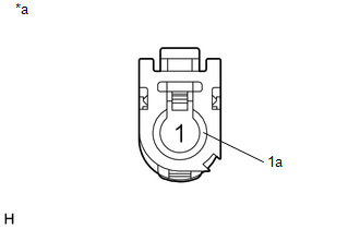
(b) Measure the resistance according to the value(s) in the table below.
Standard Resistance:
|
Tester Connection |
Condition |
Specified Condition |
|---|---|---|
|
1 - 1a |
Always |
50 to 500 Ω |
|
*a |
Component without harness connected (Navigation Antenna Assembly) |
| OK | |
REPLACE RADIO AND DISPLAY RECEIVER ASSEMBLY |
| NG | |
REPLACE NAVIGATION ANTENNA ASSEMBLY |
 Speaker Output Short (B15C3)
DESCRIPTION
This DTC is stored when a malfunction occurs in the speakers.
DTC No.
DTC Detection Condition
Trouble Area
B15C3
A short is d ...
 XM Tuner Malfunction (B15BA)
DESCRIPTION
These DTCs are stored when a malfunction occurs in the stereo component tuner
assembly.
DTC No.
DTC Detection Condition
Trouble Area
B ...
Other materials about Toyota Venza:
Ultrasonic Sensor(for Front Side)
Components
COMPONENTS
ILLUSTRATION
Removal
REMOVAL
PROCEDURE
1. REMOVE FRONT BUMPER ASSEMBLY
(See page )
2. REMOVE NO. 1 ULTRASONIC SENSOR
(a) Disengage the 2 claws to remove the No. 1 ultrasonic sensor.
HINT:
Use the same proc ...
Diagnosis System
DIAGNOSIS SYSTEM
1. DESCRIPTION
(a) Push-button start function data and the Diagnostic Trouble Codes (DTCs) can
be read through the Data Link Connector 3 (DLC3) of the vehicle. When the function
seems to be malfunctioning, use the Techstream to check for ...
Brake fluid
- Checking fluid level
The brake fluid level should be between the “MAX” and “MIN” lines on the tank.
Make sure to check the fluid type and prepare the necessary items.
- Adding fluid
- Brake fluid can absorb moisture from the ...

0.1253