Toyota Venza: Components
COMPONENTS
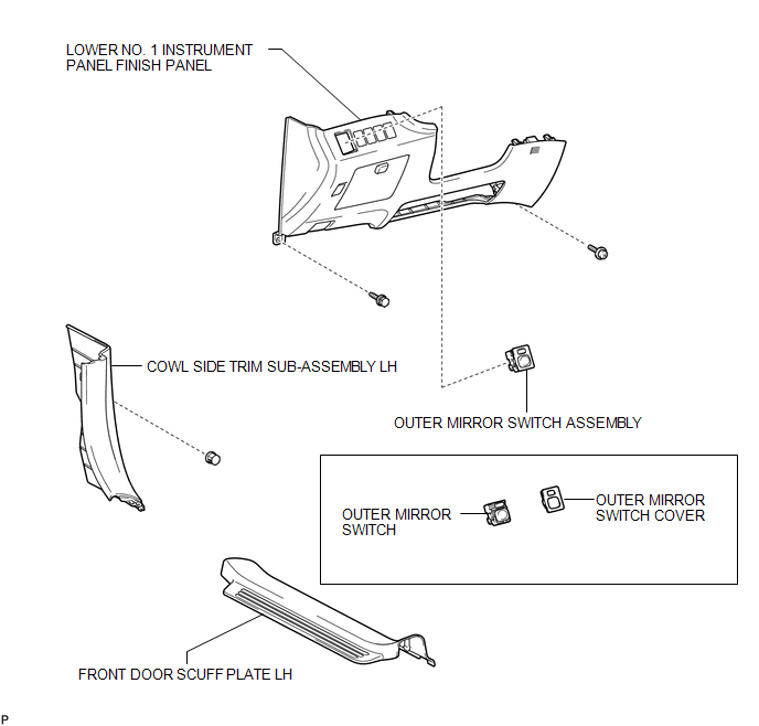
ILLUSTRATION

 Removal
REMOVAL
PROCEDURE
1. REMOVE FRONT DOOR SCUFF PLATE LH
2. REMOVE COWL SIDE TRIM SUB-ASSEMBLY LH
3. REMOVE LOWER NO. 1 INSTRUMENT PANEL FINISH PANEL
4. REMOVE OUTER MIRROR SWITCH ASSEMBLY
...
Other materials about Toyota Venza:
Slip Indicator Light Remains ON
DESCRIPTION
The skid control ECU is connected to the combination meter via CAN communication.
The slip indicator light blinks during VSC and/or TRAC operation.
When the system fails, the slip indicator light comes on to warn the driver (See
page ).
WIRI ...
Power back door switch (vehicles with power back door)
Push the switch to close.
Pressing the switch again while the power back door is closing will cause it
to open again.
However, the reverse operation cannot be performed for the first second after
pressing the switch to close the door.
The back door ca ...
Pressure Sensor Circuit (B1423/23)
DESCRIPTION
This DTC is output when refrigerant pressure on the high pressure side is extremely
low (190 kPa (1.9 kgf/cm2, 28 psi) or less) or extremely high (3140 kPa (32.0 kgf/cm2,
455 psi) or more). The A/C pressure sensor is installed on the high pres ...

0.1331