Toyota Venza: Removal
REMOVAL
PROCEDURE
1. REMOVE COOL AIR INTAKE DUCT SEAL
|
(a) Using a clip remover, remove the 12 clips and cool air intake duct seal. |
|
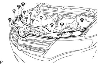
2. REMOVE RADIATOR GRILLE
.gif)
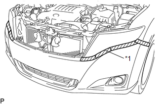
3. REMOVE FRONT BUMPER ASSEMBLY
|
(a) Put protective tape around the front bumper assembly. Text in Illustration
|
|
|
(b) Remove the 2 bolts and 6 screws. |
|
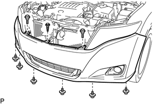
(c) Using a clip remover, remove the clip.
|
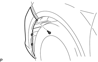
(d) Remove the screw. HINT: Use the same procedure for the RH side and LH side. |
|
|
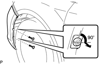
(e) Using a screwdriver, turn the 2 pins 90 degrees and remove the 2 pin hold clips. HINT: Use the same procedure for the RH side and LH side. |
|
|
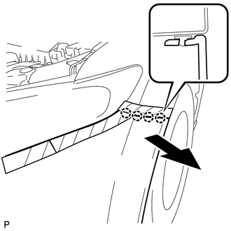
(f) Disengage the 4 claws and remove the front bumper assembly. HINT: Use the same procedure for the RH side and LH side. |
|
(g) Disconnect each connector.
|
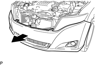
(h) Remove the front bumper assembly as shown in the illustration. |
|
 Components
COMPONENTS
ILLUSTRATION
ILLUSTRATION
ILLUSTRATION
ILLUSTRATION
...
 Disassembly
DISASSEMBLY
PROCEDURE
1. REMOVE NO. 1 ULTRASONIC SENSOR (w/ Intuitive Parking Assist System)
2. REMOVE NO. 2 ULTRASONIC SENSOR RETAINER (w/ Intuitive Parking Assist System)
3. REMOVE FRONT L ...
Other materials about Toyota Venza:
Removal
REMOVAL
PROCEDURE
1. REMOVE REAR DOOR SCUFF PLATE RH
HINT:
Use the same procedure for the RH side and the LH side (See page
).
2. REMOVE REAR DOOR OPENING TRIM WEATHERSTRIP RH
HINT:
Use the same procedure for the RH side and the LH side (See page
). ...
Front Airbag Sensor LH Malfunction (B1615/14)
DESCRIPTION
The front airbag sensor LH circuit consists of the center airbag sensor assembly
and front airbag sensor LH.
The front airbag sensor LH detects impacts to the vehicle and sends signals to
the center airbag sensor assembly to determine if the ...
System Description
SYSTEM DESCRIPTION
1. POWER MIRROR CONTROL SYSTEM DESCRIPTION
(a) This system has the following functions: power retract mirror function*,
reverse shift-linked function, electrical remote control function, memory function
and mirror heater function.
...

0.1385