Toyota Venza: Removal
REMOVAL
CAUTION / NOTICE / HINT
NOTICE:
- Do not replace the spiral cable with the battery connected and the ignition switch ON.
- Do not rotate the spiral cable without the steering wheel with the battery connected and the ignition switch ON.
- Ensure that the steering wheel is installed and aligned straight when inspecting the steering sensor.
PROCEDURE
1. TURN FRONT WHEELS TO FACE STRAIGHT AHEAD
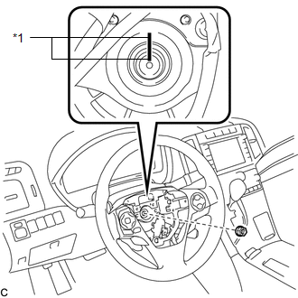
2. REMOVE STEERING PAD
(See page .gif) )
)
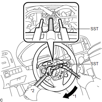
3. REMOVE STEERING WHEEL ASSEMBLY
|
(a) Remove the steering wheel assembly set nut. Text in Illustration
|
|
(b) Put matchmarks on the steering wheel assembly and the steering main shaft.
(c) Disconnect each connector from the spiral cable sub-assembly.
|
(d) Using SST, remove the steering wheel assembly. Text in Illustration
SST: 09950-50013 09951-05010 09952-05010 09953-05020 09954-05070 NOTICE:
|
|
4. REMOVE STEERING PAD SWITCH ASSEMBLY
|
(a) Remove the 2 screws. Text in Illustration
|
|
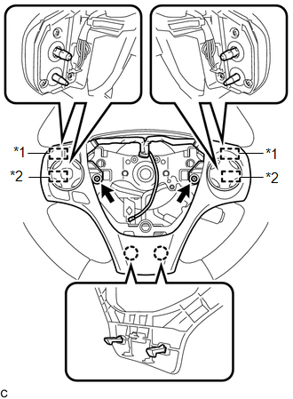
(b) Disengage the 2 claws, 2 pins and 2 guides to remove the steering pad switch assembly.
5. REMOVE CRUISE CONTROL MAIN SWITCH
6. REMOVE CRUISE CONTROL SWITCH WIRE
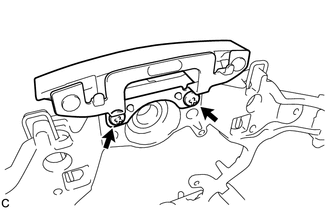
7. REMOVE STEERING SHAKE DAMPER
|
(a) Remove the 2 screws and steering shake damper from the steering wheel sub-assembly. |
|
 Inspection
INSPECTION
PROCEDURE
1. INSPECT STEERING PAD SWITCH ASSEMBLY
(a) Measure the resistance according to the value(s) in the table below.
Standard Resistance:
Tester Connection
...
 Installation
INSTALLATION
CAUTION / NOTICE / HINT
NOTICE:
Do not replace the spiral cable with the battery connected and the ignition
switch ON.
Do not rotate the spiral cable without the steeri ...
Other materials about Toyota Venza:
Precaution
PRECAUTION
1. NOTICE FOR INITIALIZATION
NOTICE:
When disconnecting the cable from the negative (-) battery terminal, initialize
the following system after the cable is reconnected.
System Name
See Procedure
Back Doo ...
Replacement
REPLACEMENT
PROCEDURE
1. REPLACE GENERATOR DRIVE END FRAME BEARING
(a) Remove the 4 screws and bearing retainer from the drive end frame.
(b) Using SST and a hammer, tap out the drive end ...
Back Door Entry Unlock Function does not Operate
DESCRIPTION
If the entry back door open function does not operate but the back door entry
lock function operates, the communication between the vehicle and key is normal.
As a faulty part, the back door open switch circuit (from the back door opener switc ...

0.1458