Toyota Venza: Removal
REMOVAL
CAUTION / NOTICE / HINT
PROCEDURE
1. PRECAUTION
NOTICE:
After turning the ignition switch off, waiting time may be required before disconnecting
the cable from the negative (-) battery terminal. Therefore, make sure to read the
disconnecting the cable from the negative (-) battery terminal notices before proceeding
with work (See page .gif) ).
).
2. DISCONNECT CABLE FROM NEGATIVE BATTERY TERMINAL
NOTICE:
When disconnecting the cable, some systems need to be initialized after the cable
is reconnected (See page ).
3. REMOVE LIGHT CONTROL ECU (for LH Side)
CAUTION:
The light control ECU may be hot when the light control switch is in the HEAD position or right after it is turned off. Check that the light control ECU is not hot before starting work.
|
(a) Disconnect the connector. |
|
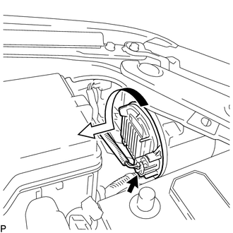
(b) Turn the light control ECU in the direction indicated by the arrow shown in the illustration, and disconnect it.
NOTICE:
- Do not apply excessive force using a tool.
- Do not damage the O-ring or allow it to become contaminated with foreign matter. If the O-ring is damaged or contaminated, water may get into the headlight assembly, resulting in a malfunction of the light control ECU.
|
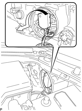
(c) Turn the socket of the light control ECU in the direction indicated by the arrow shown in the illustration, and remove it. NOTICE: Do not pull the light control ECU with the socket connected. |
|
4. REMOVE RADIATOR RESERVE TANK ASSEMBLY (for RH Side)
5. REMOVE LIGHT CONTROL ECU (for RH Side)
CAUTION:
The light control ECU may be hot when the light control switch is in the HEAD position or right after it is turned off. Check that the light control ECU is not hot before starting work.
|
(a) Disconnect the connector. |
|
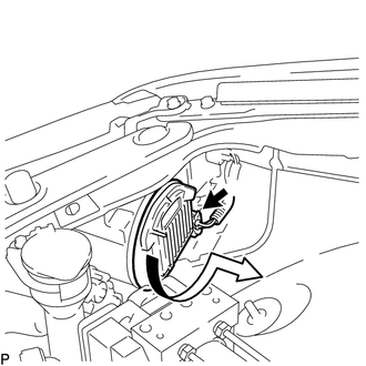
(b) Turn the light control ECU in the direction indicated by the arrow shown in the illustration, and disconnect it.
NOTICE:
- Do not apply excessive force using a tool.
- Do not damage the O-ring or allow it to become contaminated with foreign matter. If the O-ring is damaged or contaminated, water may get into the headlight assembly, resulting in a malfunction of the light control ECU.
|
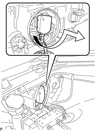
(c) Turn the socket of the light control ECU in the direction indicated by the arrow shown in the illustration, and remove it. NOTICE: Do not pull the light control ECU with the socket connected. |
|
6. REMOVE DISCHARGE HEADLIGHT BULB
HINT:
Use the same procedure for the RH side and LH side (See page
).
 Installation
INSTALLATION
PROCEDURE
1. INSTALL DISCHARGE HEADLIGHT BULB
HINT:
Use the same procedure for the RH side and LH side (See page
).
2. INSTALL LIGHT CONTROL ECU (for LH Side)
(a) Turn ...
 High Mounted Stop Light Assembly
Components
COMPONENTS
ILLUSTRATION
Removal
REMOVAL
PROCEDURE
1. REMOVE CENTER STOP LIGHT ASSEMBLY
(a) Using a short screwdriver, remove the 2 screws.
...
Other materials about Toyota Venza:
Actuator Check
ACTUATOR CHECK
1. ACTUATOR CHECK
(a) Start the engine and warm it up.
(b) Perform the indicator check (See page
).
(c) Press the "Recirculation/Fresh" switch to perform the actuator check.
HINT:
Be sure to perform the actuator check after ...
On-vehicle Inspection
ON-VEHICLE INSPECTION
PROCEDURE
1. INSPECT STEERING WHEEL FREE PLAY
(a) Stop the vehicle and position the front wheels straight ahead.
(b) Gently turn the steering wheel right and left, and check the steering wheel
free play.
Maximum free play:
30 mm ...
System Description
SYSTEM DESCRIPTION
1. GENERAL
This system has the following functions: manual slide open and close; auto slide
open; manual tilt up and down; auto tilt up; jam protection; key off operation.
2. FUNCTION OF MAIN COMPONENT
Component
O ...

0.1138