Toyota Venza: Rear Door RH ECU Communication Stop (B2323)
DESCRIPTION
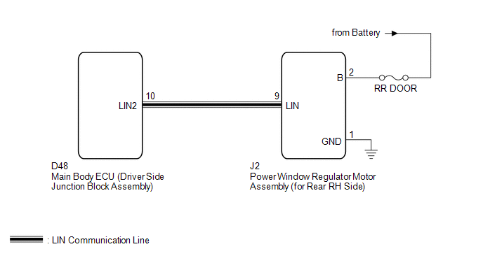
This DTC is stored when LIN communication between the power window regulator motor assembly (for rear RH side) and main body ECU (driver side junction block assembly) stops for more than 10 seconds.
|
DTC No. |
DTC Detection Condition |
Trouble Area |
|---|---|---|
|
B2323 |
No communication between the power window regulator motor assembly (for rear RH side) and main body ECU (driver side junction block assembly) for more than 10 seconds. |
|
WIRING DIAGRAM
CAUTION / NOTICE / HINT
NOTICE:
- When the power window regulator motor assembly (for rear RH side) is
replaced or removed and reinstalled, it requires initialization (See page
.gif) ).
). - When using the Techstream to troubleshoot with the ignition switch off:
Connect the Techstream to the DLC3, and turn the courtesy switch on and off at 1.5-second intervals until communication between the Techstream and vehicle begins.
PROCEDURE
|
1. |
CHECK HARNESS AND CONNECTOR (POWER WINDOW REGULATOR MOTOR - BATTERY AND BODY GROUND) |
|
(a) Disconnect the J2 motor connector. |
|
(b) Measure the resistance and voltage according to the value(s) in the table below.
Standard Resistance:
|
Tester Connection |
Condition |
Specified Condition |
|---|---|---|
|
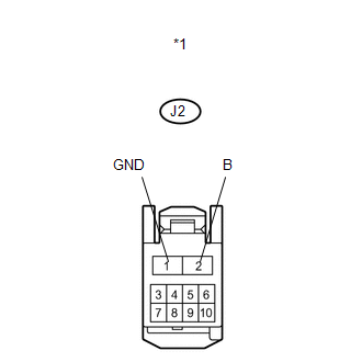
J2-1 (GND) - Body ground |
Always |
Below 1 Ω |
Standard Voltage:
|
Tester Connection |
Condition |
Specified Condition |
|---|---|---|
|
J2-2 (B) - Body ground |
Always |
11 to 14 V |
|
*1 |
Front view of wire harness connector (to Power Window Regulator Motor Assembly (for Rear RH Side)) |
| NG | .gif) |
REPAIR OR REPLACE HARNESS OR CONNECTOR |
|
.gif)
|
2. |
CHECK HARNESS AND CONNECTOR (MAIN BODY ECU - POWER WINDOW REGULATOR MOTOR ASSEMBLY) |
|
(a) Disconnect the D48 ECU connector. |
|
(b) Measure the resistance according to the value(s) in the table below.
Standard Resistance:
|
Tester Connection |
Condition |
Specified Condition |
|---|---|---|
|
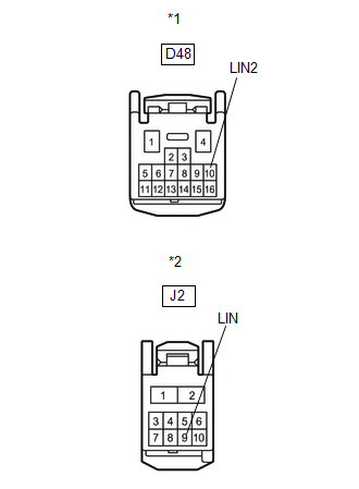
D48-10 (LIN2) - J2-9 (LIN) |
Always |
Below 1 Ω |
|
D48-10 (LIN2) - Body ground |
Always |
10 kΩ or higher |
|
*1 |
Front view of wire harness connector (to Main Body ECU (Driver Side Junction Block Assembly)) |
|
*2 |
Front view of wire harness connector (to Power Window Regulator Motor Assembly (for Rear RH Side)) |
| NG | |
REPAIR OR REPLACE HARNESS OR CONNECTOR |
|
|
3. |
REPLACE POWER WINDOW REGULATOR MOTOR ASSEMBLY (for REAR RH SIDE) |
(a) Replace the power window regulator motor assembly (for rear RH side) (See
page ).
|
|
4. |
CHECK DTC OUTPUT |
(a) Clear the DTC (See page ).
(b) Recheck for DTCs.
OK:
DTC B2323 is not output.
| OK | |
END (POWER WINDOW REGULATOR MOTOR ASSEMBLY WAS DEFECTIVE) |
| NG | |
REPLACE MAIN BODY ECU (DRIVER SIDE JUNCTION BLOCK ASSEMBLY) |
 Front Passenger Side Door ECU Communication Stop (B2322)
DESCRIPTION
This DTC is stored when LIN communication between the power window regulator
motor assembly (for front passenger side) and main body ECU (driver side junction
block assembly) stops fo ...
 Driver Side Door ECU Communication Stop (B2321)
DESCRIPTION
This DTC is stored when LIN communication between the power window regulator
motor assembly (for driver side) and main body ECU (driver side junction block assembly)
stops for more th ...
Other materials about Toyota Venza:
Front passenger occupant classification system
Your vehicle is equipped with a front passenger occupant classification system.
This system detects the conditions of the front passenger seat and activates or
deactivates the devices for front passenger.
1. SRS warning light
2. Front passenger’s sea ...
Seat Heater Control
Components
COMPONENTS
ILLUSTRATION
Installation
INSTALLATION
PROCEDURE
1. INSTALL SEAT HEATER CONTROL SUB-ASSEMBLY
(a) Engage the clamp and install the seat heater control sub-assembly.
(b ...
ECU Power Source Circuit
DESCRIPTION
This circuit provides power for main body ECU (driver side junction block assembly)
operation.
WIRING DIAGRAM
PROCEDURE
1.
CHECK DRIVER SIDE JUNCTION BLOCK ASSEMBLY (MAIN BODY ECU (POWER SOURCE))
...

0.1351