Toyota Venza: Inspection
INSPECTION
PROCEDURE
1. INSPECT STEERING PAD SWITCH ASSEMBLY
(a) Measure the resistance according to the value(s) in the table below.
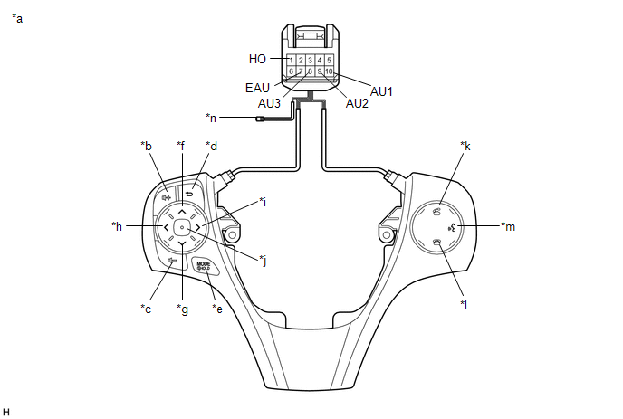
Standard Resistance:
|
Tester Connection |
Condition |
Specified Condition |
|---|---|---|
|
1 (HO) - Terminal-A |
Always |
Below 1 Ω |
|
10 (AU1) - 7 (EAU) |
No switch pushed |
95 to 105 kΩ |
|
Up switch pushed |
Below 2.5 Ω |
|
|
Down switch pushed |
313 to 345 Ω |
|
|
Volume+ switch pushed |
950 to 1050 Ω |
|
|
Volume- switch pushed |
2955 to 3265 Ω |
|
|
9 (AU2) - 7 (EAU) |
No switch pushed |
95 to 105 kΩ |
|
MODE/HOLD switch pushed |
Below 2.5 Ω |
|
|
On hook switch pushed |
313 to 345 Ω |
|
|
Off hook switch pushed |
950 to 1050 Ω |
|
|
Voice switch pushed |
2955 to 3265 Ω |
|
|
8 (AU3) - 7 (EAU) |
No switch pushed |
95 to 105 kΩ |
|
Enter switch pushed |
Below 2.5 Ω |
|
|
Back switch pushed |
313 to 345 Ω |
|
|
Right switch pushed |
950 to 1050 Ω |
|
|
Left switch pushed |
2955 to 3265 Ω |
HINT:
If the result is not as specified, replace the steering pad switch assembly.
Text in Illustration|
*a |
Component without harness connected (Steering Pad Switch Assembly) |
*b |
Volume+ |
|
*c |
Volume- |
*d |
Back |
|
*e |
MODE/HOLD |
*f |
Up |
|
*g |
Down |
*h |
Left |
|
*i |
Right |
*j |
Enter |
|
*k |
Off hook |
*l |
On hook |
|
*m |
Voice |
*n |
Terminal-A |
(b) Check the illumination.
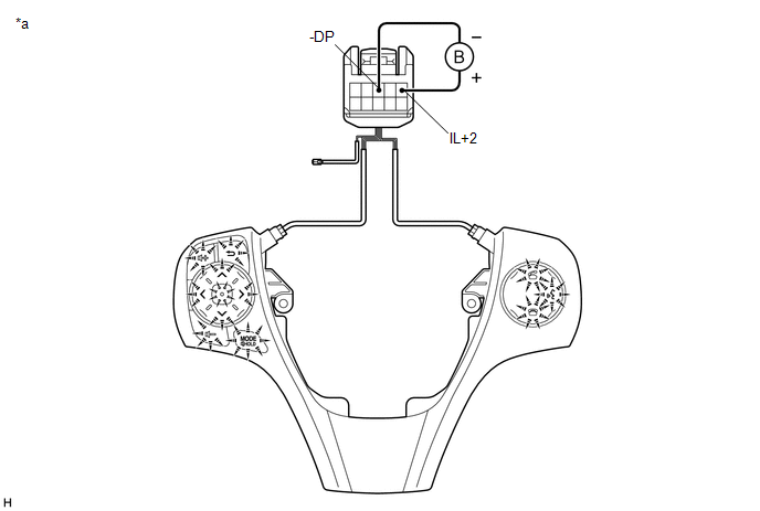
(1) Connect a battery positive (+) lead to terminal IL+2 and a negative (-) lead to terminal -DP of the steering pad switch assembly connector.
(2) Check that the switch illumination comes on.
OK:
Steering pad switch illumination comes on.
HINT:
If the result is not as specified, replace the steering pad switch assembly.
Text in Illustration|
*a |
Component without harness connected (Steering Pad Switch Assembly) |
- |
- |
 Components
COMPONENTS
ILLUSTRATION
ILLUSTRATION
...
 Removal
REMOVAL
CAUTION / NOTICE / HINT
NOTICE:
Do not replace the spiral cable with the battery connected and the ignition
switch ON.
Do not rotate the spiral cable without the steering wh ...
Other materials about Toyota Venza:
Battery
- Battery exterior
Make sure that the battery terminals are not corroded and that there are no loose
connections, cracks, or loose clamps.
1. Terminals
2. Hold-down clamp
- Before recharging
When recharging, the battery produces hydrogen g ...
Reassembly
REASSEMBLY
PROCEDURE
1. INSTALL GENERATOR ROTOR ASSEMBLY
(a) Place the generator drive end frame on the generator pulley.
(b) Install the generator rotor to the generator drive end frame.
...
Interior Light Auto Cut Circuit
DESCRIPTION
When battery saving control operates while the interior lights are on, the main
body ECU (driver side junction block assembly) opens the DOME CUT relay to turn
off the lights.
WIRING DIAGRAM
CAUTION / NOTICE / HINT
NOTICE:
Inspect the fu ...

0.1234