Toyota Venza: Removal
REMOVAL
PROCEDURE
1. REMOVE UPPER CONSOLE PANEL SUB-ASSEMBLY (w/o Seat Heater System)
.gif)
2. REMOVE UPPER CONSOLE PANEL SUB-ASSEMBLY (w/ Seat Heater System)
3. REMOVE NO. 2 CONSOLE BOX CARPET
4. REMOVE CONSOLE BOX ASSEMBLY
5. REMOVE AIR CONDITIONING CONTROL ASSEMBLY
6. REMOVE FRONT DOOR SCUFF PLATE LH
7. REMOVE COWL SIDE TRIM SUB-ASSEMBLY LH
8. REMOVE LOWER NO. 1 INSTRUMENT PANEL FINISH PANEL
9. REMOVE FRONT DOOR SCUFF PLATE RH
HINT:
Use the same procedure for the RH side and LH side (See page
).
10. REMOVE COWL SIDE TRIM SUB-ASSEMBLY RH
HINT:
Use the same procedure for the RH side and LH side (See page
).
11. REMOVE NO. 2 INSTRUMENT PANEL UNDER COVER SUB-ASSEMBLY
12. REMOVE LOWER INSTRUMENT PANEL SUB-ASSEMBLY
13. REMOVE SHIFT LEVER KNOB SUB-ASSEMBLY
14. REMOVE POSITION INDICATOR HOUSING ASSEMBLY
15. REMOVE CONSOLE BOX SUB-ASSEMBLY
16. REMOVE NO. 2 INSTRUMENT PANEL SPEAKER PANEL SUB-ASSEMBLY
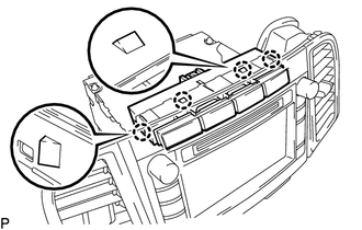
17. REMOVE RADIO AND DISPLAY RECEIVER ASSEMBLY WITH BRACKET (for Radio and Display Type)
18. REMOVE NAVIGATION RECEIVER ASSEMBLY WITH BRACKET (for Navigation Receiver Type)
19. REMOVE DRIVE MONITOR SWITCH
|
(a) Disengage the 4 claws and remove the drive monitor switch. |
|
 Inspection
INSPECTION
PROCEDURE
1. INSPECT DRIVE MONITOR SWITCH
(a) Measure the resistance according to the value(s) in the table below.
Standard Resistance:
Tester Connection
Condi ...
 Installation
INSTALLATION
PROCEDURE
1. INSTALL DRIVE MONITOR SWITCH
(a) Engage the 4 claws to install the drive monitor switch.
2. INSTALL RADIO AND DISPLAY RECEIVER ASSEMBLY WITH BRACKET (for Radio and Displa ...
Other materials about Toyota Venza:
Installation
INSTALLATION
PROCEDURE
1. INSTALL FRONT DOOR LOCK ASSEMBLY
NOTICE:
When reusing the removed front door lock assembly, replace the door
lock wiring harness seal on the connector with a new one.
Do not allow grease or dust to adhere to the do ...
Back Door Courtesy Switch
Components
COMPONENTS
ILLUSTRATION
Removal
REMOVAL
PROCEDURE
1. REMOVE BACK DOOR PANEL TRIM ASSEMBLY
2. REMOVE BACK DOOR LOCK ASSEMBLY
(a) Disconnect the connector.
(b) Disengage the c ...
Engine compartment
► 2GR-FE engine
1. Engine coolant reservoir
2. Engine oil filler cap
3. Engine oil level dipstick
4. Brake fluid reservoir
5. Battery
6. Fuse box
7. Electric cooling fans
8. Condenser
9. Radiator
10.Washer fluid tank
► 1AR-FE engine
...

0.1671